Integrated Multi-Zone Wastewater Treatment System And Method

a wastewater treatment system and multi-zone technology, applied in biological water/sewage treatment, sustainable biological treatment, membrane technology, etc., can solve problems such as threatening aquatic life, suspended growth biological treatment system, and difficulty in maintaining an adequate concentration of active biomass, and achieve the effect of efficient removal

Active Publication Date: 2008-05-15
BIOCAST SYSTEMS INC
View PDF8 Cites 41 Cited by
  • Summary
  • Abstract
  • Description
  • Claims
  • Application Information

AI Technical Summary

Benefits of technology

[0033]It is an object of the invention to provide a wastewater treatment apparatus capable of efficiently removing organic contaminants

Problems solved by technology

Nitrogen and phosphorus have been recognized as major contributors to eutrophication, a process that supports the growth of algae and other undesirable organisms in the receiving waters and diminishes the concentration of dissolved oxygen, thus threatening aquatic life.
Suspended-growth biological treatment systems that are based on activated sludge processes have difficulties in maintaining an adequate concentration of active biomass, and to effectively separate solids from liquid.
They also produce large amounts of sludge and have a slow adaptation to fluctuating influent conditions.
Aerobic fixed-film systems treating high organic concentrations have a limited capacity because of oxygen transfer limitations.
Moreover, the build-up of a thick and heavy biofilm, resulting from high concentrations of organic substances may cause clogging, seriously disrupting the operation of the treatment system.
Therefore, fixed-film systems have a limited application in the treatment of high organic load wastewaters.
Another disadvantage of fixed-film treatment systems is that they usually operate in plug-flow mode and do not offer the homogenous environment provided by completely mixed reactors.
In these systems, there is a high concentration of contaminants at the influent end of the reactor and the microorganisms will be subjected to the full concentration of contaminants that may be toxic.
These technologies also cannot stabilize the produced sludge and need supplementary vessels for this process.
These modifications have increased the complexity of the treatment systems and complicated their proper design and optimization.
As learned from the above description, most conven

Method used


Image

  • Integrated Multi-Zone Wastewater Treatment System And Method
  • Integrated Multi-Zone Wastewater Treatment System And Method
  • Integrated Multi-Zone Wastewater Treatment System And Method

Examples


Embodiment Construction

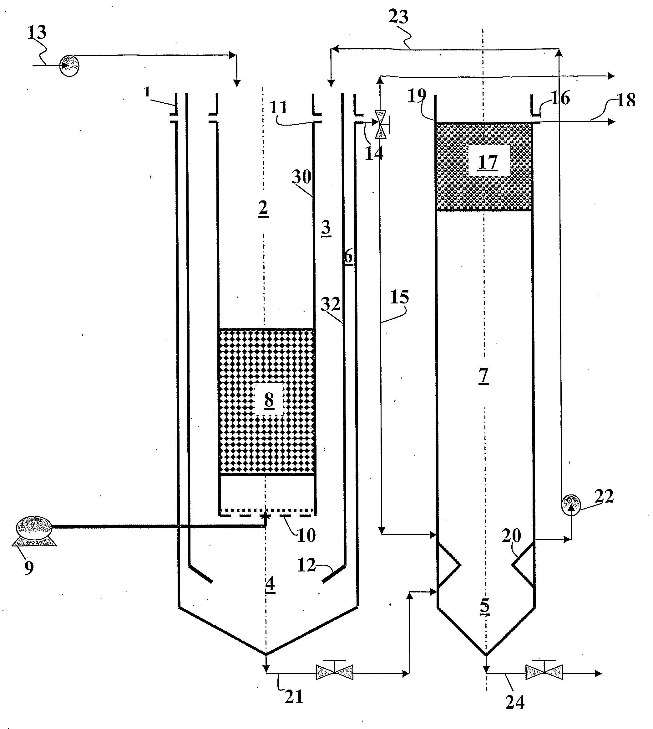
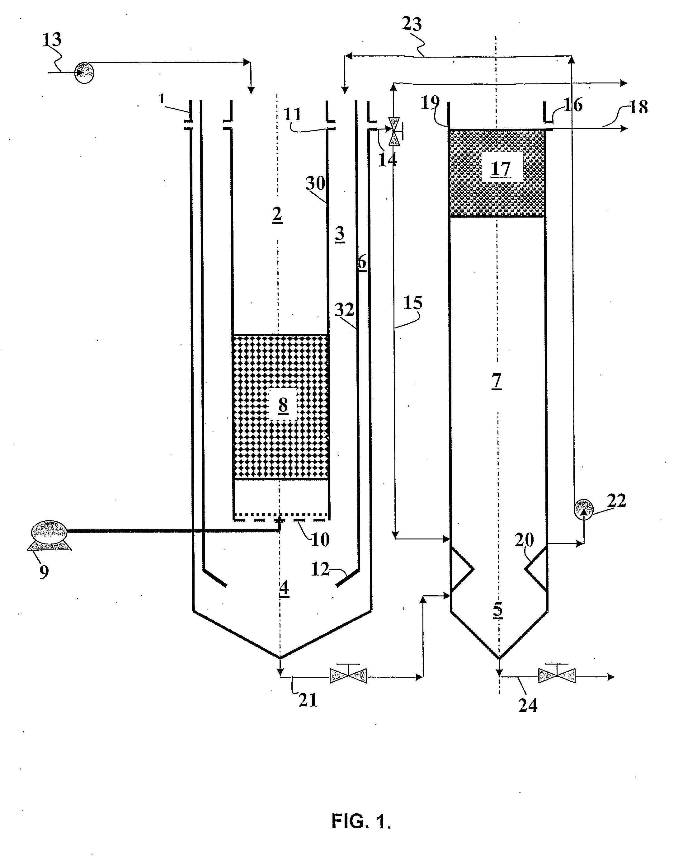
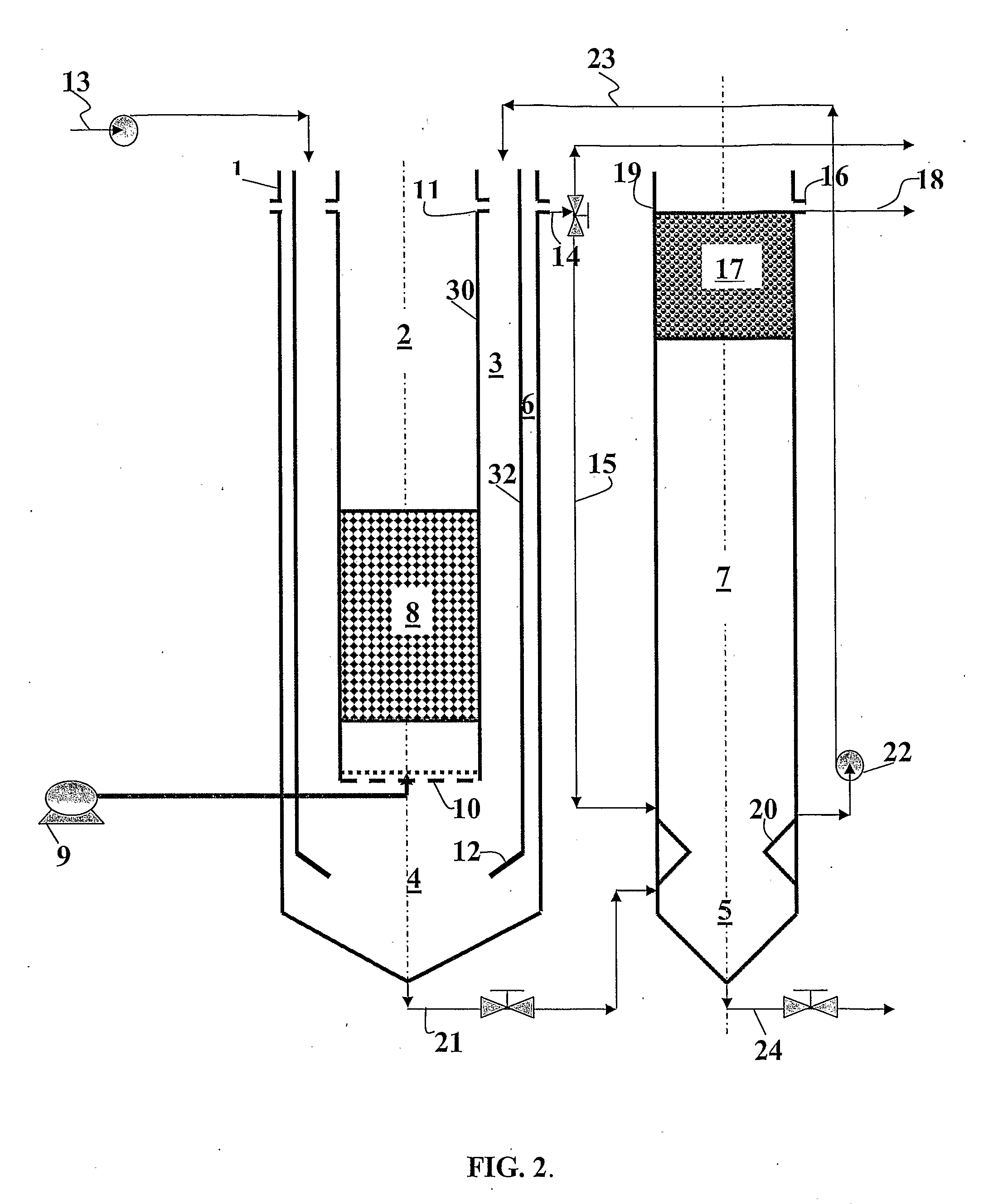
[0053]As stated above, the treatment system of the present invention uses two separate but interlinked tanks for the biological treatment and solid-liquid separation processes. The first tank contains an aerobic zone, microaerophilic and anoxic zone plus a clarification zone. The second tank contains an anaerobic zone, a solid-liquid separation zone and a filtration unit. An example of the treatment system according to the invention is presented in FIG. 1.

[0054]It will be noted that in the embodiments described herein, the anaerobic zone is disposed in a different vessel than the aerobic zone and the oxygen-depleted zone(s).

[0055]The wastewater is introduced into the first tank 1 containing an aerobic zone 2, microaerophilic zone 3 and anoxic zone 4. The separation of solids from liquid takes place in two clarification zones 6 and 7, the first zone 6 attached to the microaerophilic zone 3, and the second zone 7 located in the second tank 19 disposed downstream of the first tank 1 an...


PUM


Abstract

A wastewater treatment system has two separate but interlinked tanks containing four different zones, namely aerobic, microaerophilic, anoxic and anaerobic, for the biological treatment of the wastewater, as well as two clarification zones and a filtration unit for separation of solids from liquid. The first tank contains the aerobic, microaerophilic and anoxic zone as well as a clarification zone, while the second dank includes the anaerobic zone, a solid-liquid separation zone and a filtration unit. The aerobic zone is an airlift reactor that contains air diffusers at the bottom of the zone to introduce air into the zone. The air bubbles mix the liquid and its content of microorganisms, and provide oxygen for the aerobic biological processes that take place in this zone. Aeration also produces circulation of liquid between the aerobic zone and its adjacent microaerophilic and anoxic zones that are located at the sides and under the aerobic zone, respectively. The aerobic zone contains suspended microorganisms of heterotrophic and autotrophic groups that grow inside the circulating liquid, known as mixed liquor. Within the volume of the aerobic zone, loose carrier material or stationary objects are disposed to support the attachment of microbial biomass and the formation of microbial biofilm.

Description

FIELD OF THE INVENTION[0001]The method and apparatus of this invention relate to the treatment of a liquid or slurry of waste stream (e.g., wastewater or sludge) originated from municipal or industrial activities, or the treatment of groundwater or landfill leachate contaminated with organic and / or inorganic chemicals. The organic material may contain sources of BOD and COD as well as hazardous chemicals such as aromatic hydrocarbons, including benzene, toluene, ethylbenzene, xylenes, phenols, cresols, polycyclic aromatic hydrocarbons (PAHs), and halogenated (e.g., chlorinated) hydrocarbons, such as tetrachloroethylene, trichloroethylene, 1,1,1-trichloroethane and similar xenobiotics, and inorganic material notably nitrogen and phosphorus.BACKGROUND OF THE INVENTION[0002]The treatment of wastewater and contaminated groundwater require the removal of organic and inorganic contaminants, usually present in solid and / or dissolved form, before their discharge into the receiving waters. T...

Claims


Application Information

Patent Timeline
IPC IPC(8): C02F3/02
CPCC02F3/06C02F3/223Y10S210/906C02F3/301C02F3/30Y02W10/10
Inventor YERUSHALMI, LALEHOGILVIE, MICHAEL J.
Owner BIOCAST SYSTEMS INC
Why Eureka
Try Eureka