It is not surprising therefore that the electrical
system in a vehicle is by far the most unreliable
system of the vehicle and the probable cause of most warranty repairs.
Unfortunately, the automobile industry is taking a piecemeal approach to solving this problem when a revolutionary approach is called for.
Most airbag modules in use today are large, heavy, expensive, and inefficient.
As a result, airbags are now primarily only used for protecting the passenger and driver in a frontal
impact, although at least three automobile manufacturers currently offer a small airbag providing limited protection in side impacts and some are now offering head protection airbags.
One reason for this is that there is a mismatch between the output of a burning
propellant and the inflation requirements of an airbag.
Airbags, on the other hand, need gases with low temperatures and low pressures and high gas flow rates.
Other systems have attempted to use aspiration techniques, but because of the geometry constraints of current car inflator designs and mounting locations, and for other reasons, currently used aspiration systems are only able to draw significantly less than 30% of the gas needed to inflate an airbag from the passenger compartment.
Furthermore, since inflators are large and inefficient, severe restrictions have been placed on the type of propellants that can be used since the
combustion products of the
propellant must be breathable by automobile occupants.
It is of little value to save an occupant from death in an
automobile accident only to suffocate him from an excessive amount of
carbon dioxide in the air within the passenger compartment after the accident.
This
residual mass is very hot and requires the inflator to be mounted away from combustible materials further adding to the
mass and size of the airbag system and restricts the materials that can be used for the inflator.
It is a persistent problem in the art that many people are being seriously injured or even killed today by the airbag itself.
One reason that this is such a significant problem is that the airbag module itself is quite large and, in particular, the airbags are made out of thick, heavy material and packaged in a poor, folded geometry.
All of this heavy airbag material must be rolled and folded inside this comparatively small module, thus requiring substantial energy to unfold during deployment.
Even the time to deploy the airbag is substantially affected by the
mass of the airbag material and the need to unfold an airbag with a complicated folding pattern.
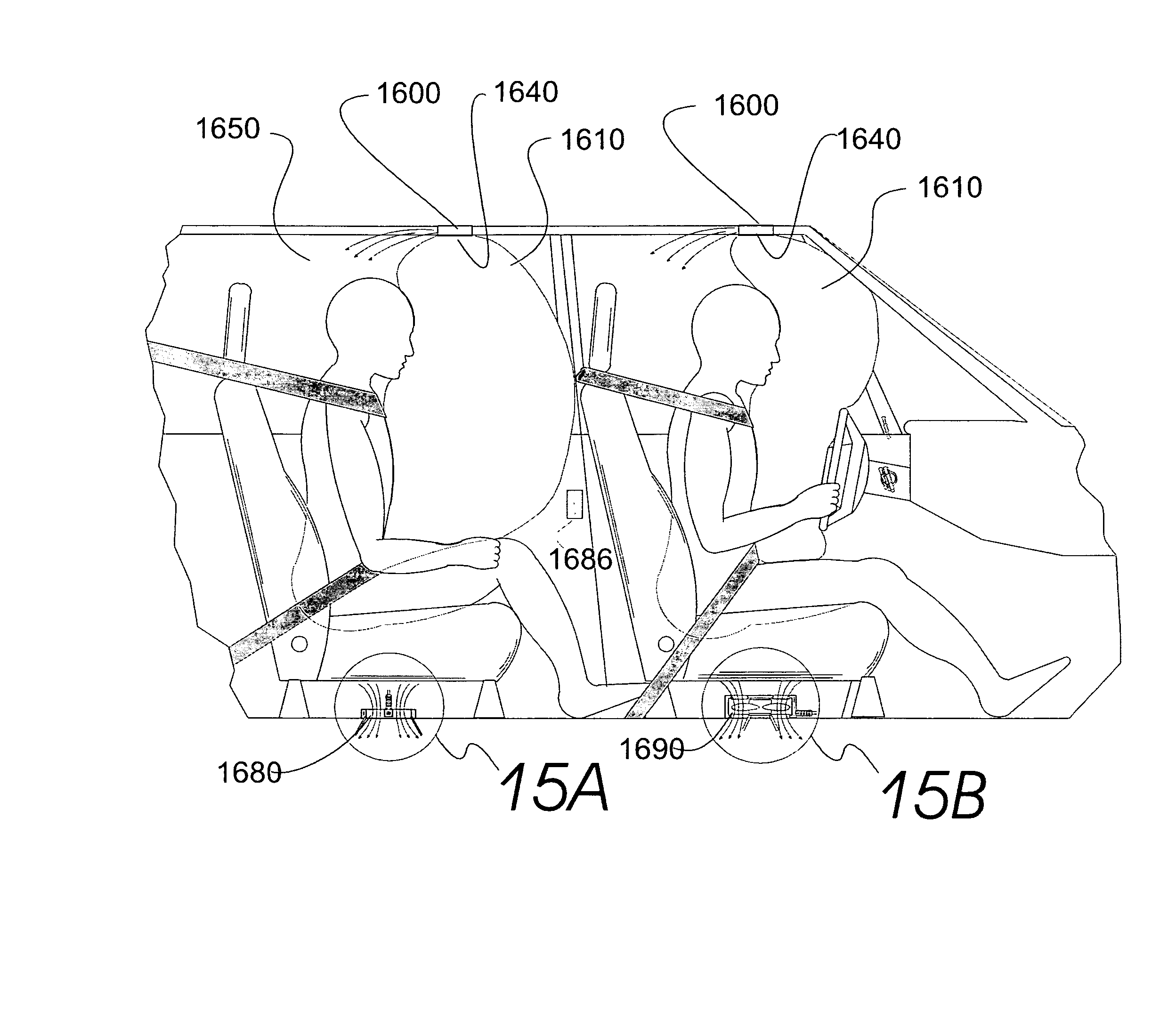
One problem with ceiling mounted airbags is that the distance required for the airbag to travel, in some cases, is longer and therefore a larger airbag is needed with greater
deployment time.
The driver poses a different problem since it would be difficult to position a ceiling mounted airbag module where the airbag would always be projected properly between the occupant and the
steering wheel.
This problem for the driver's airbag system is not the concept of mounting the airbag on the ceiling, but the design of the
steering wheel and
steering column.
The majority of vehicles manufactured today have power assisted steering systems and, in fact, most drivers would have difficulty steering a car today if the
power steering failed.
Small people, for example, who are wearing seatbelts can still be seriously injured or killed in accidents as their faces slam into the steering wheel hubs.
The problem of properly positioning an airbag, when the comfort and convenience features of telescoping and tilting steering columns are considered, results in substantial safety compromises.
Deployment induced injuries which result when a small person is close to the steering wheel when the airbag deploys have already caused several deaths and numerous serious injuries.
In some accidents, an occupant, and particularly a center-seated occupant, can pass between the two airbags and not receive the full protection from either one.
Although analysis indicates that pumping ratios of 4:1 or 5:1 would be difficult to achieve with this design as illustrated, nevertheless, this reference illustrates the size and rough shape of an aspirating system which is required to obtain high pumping ratios using the prior art designs.
No attempt has been made in this design to optimize the
nozzle geometry to make use of a converging-diverging
nozzle design, for example.
Analysis shows, however, that the opening needed for the claimed aspiration ratios would in general be far too large for it also to be used for exhausting the airbag during a
crash.
This design also does not require use of aspiration valves which is more reasonable for this case, but still unlikely, since the aspiration port area is much smaller.
Again, no attempt has been made to optimize the
nozzle design as is evident by the short nozzle length and the low pumping ratio.
Analysis has shown that this is the case, that is, that such large aspiration ratios are not achievable with the prior art designs.
Once again, little attempt has been made to optimize the nozzle design.
The lack of commercial success of these two Hayashi patents is probably due to the fact that such high pumping ratios as claimed are not in fact achievable in the geometries illustrated.
This system however produces a gas which is too hot for use directly to inflate an airbag.
The steam can cause burns to occupants and
carbon dioxide in significant quantities is toxic.
Nevertheless, the airbag system disclosed is quite large and limited in length such that the flow passageways are quite large which requires a long nozzle design for efficient operation.
No analysis, however, is provided to prove that the area of the aspiration holes is comparable to the area of the exhaust holes normally provided in the airbag.
Again the nozzle design has not been optimized.
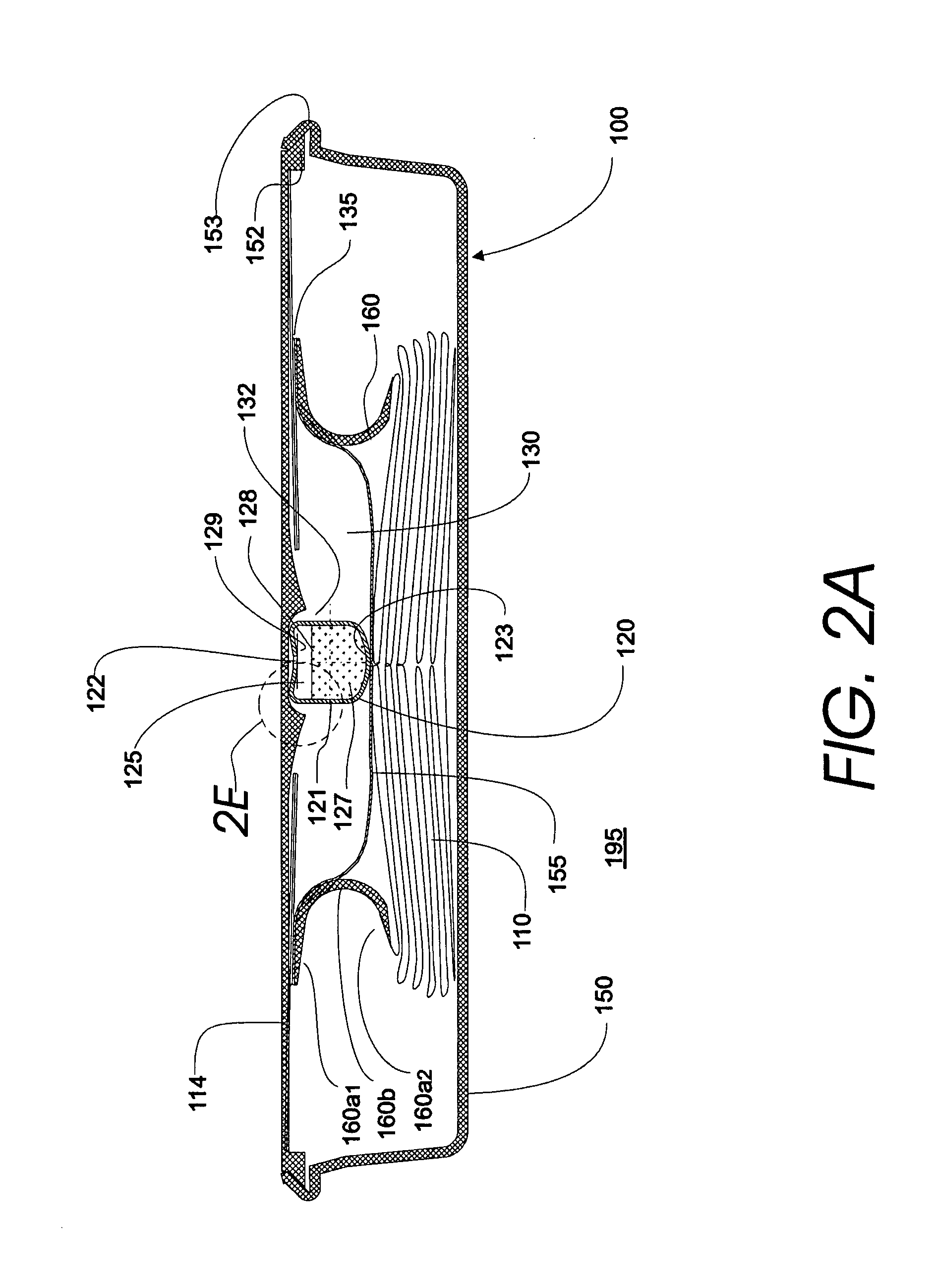
None of the prior art inflators contain the advantages of the combination of (i) a linear inflator having a small cross section thereby permitting an efficient nozzle design wherein the length of the nozzle is much greater than the aspiration port opening, (ii) a non
sodium azide propellant which may produce
toxic gas if not diluted with substantial quantities of
ambient air, and (iii) an inflator where minimal or no filtering or heat absorption is required.
It is interesting to note that in
spite of the large aspiration pumping ratios mentioned and even claimed in the prior art references mentioned above, and to the very significant advantages which would result if such ratios could be achieved, none has been successfully adapted to an automobile airbag system.
One reason is that pumping ratios which are achievable in a
steady state laboratory environment are more difficult to achieve in the transient conditions of an actual
airbag deployment.
None of these prior art designs have resulted in a thin linear module which permits the space necessary for an efficient nozzle design as disclosed herein.
In
spite of the many advantages claimed in the prior art patents, none have resulted in a module which can be mounted within the vehicle headliner trim, for example, or can be made to conform to a curved surface.
In fact, the rigid shape of conventional airbag modules has forced the vehicle interior designers to compromise their designs since the surface of such modules must be a substantially flat plane.
However, Nissan has stated that it cannot provide more than a total of two airbags in the vehicle and that it will not offer a front passenger side airbag for those vehicles that have a rear seat airbag.
With respect to the Volvo,
General Motors and Ford airbags, these side airbags will not deploy when the frontal airbags do because if more than two airbags would be deployed in a vehicle at the same time, the pressure generated by the deploying airbags within the passenger compartment of the vehicle creates large forces on the
doors.
These forces may be sufficient to force the
doors open and consequently, if the
doors of the vehicle are forced open during a
crash, vehicle occupants might be ejected, greatly increasing the likelihood of serious injury.
In addition, the pressure generated within the passenger compartment creates excessive
noise which can injure human beings.
In addition to airbags for side impacts and rear seats, it is likely that airbags will be used as knee bolsters since automobile manufacturers are having serious problems protecting knees from injury in crashes while providing the comfort space desired by their customers.
This is partially due to the fact that when
sodium azide burns, in the presence of an oxidizer, it produces large amounts of
Nitrogen gas.
It also produces
sodium oxide which must be retained in the inflator since
sodium oxide, when mixed with
moisture, becomes lye and is very toxic to humans.
In many cases, the gases produced by these other propellants are only toxic to humans if breathed over an extended period of time.
It is believed that in all current designs, a substantial amount of the energy in a propellant is lost through this cooling process which in turn necessitates that the inflator contain more propellant.
As a result, although numerous attempts have been made to create aspirated inflator systems, they have only been used on the passenger side and their efficiency has been low.
In view of the
large size of conventional
sodium azide inflators and woven airbags, there is limited room for the airbag system and it is difficult to design aspirating systems which will fit within the remaining available space.
Another reason for the low efficiency of aspirated inflator systems is that the aspirated systems used today have inefficient nozzle designs.
Poole et al. does not suggest that the outside air should come from the passenger compartment and therefore does not provide a solution to the problem of excessive pressure being generated in the passenger compartment upon deployment of multiple airbags, as discussed above.
This has resulted in many failures of the airbag system due to shorted wires and other related causes.

