[0012]A further
advantage of the present invention is that it is often advantageous to
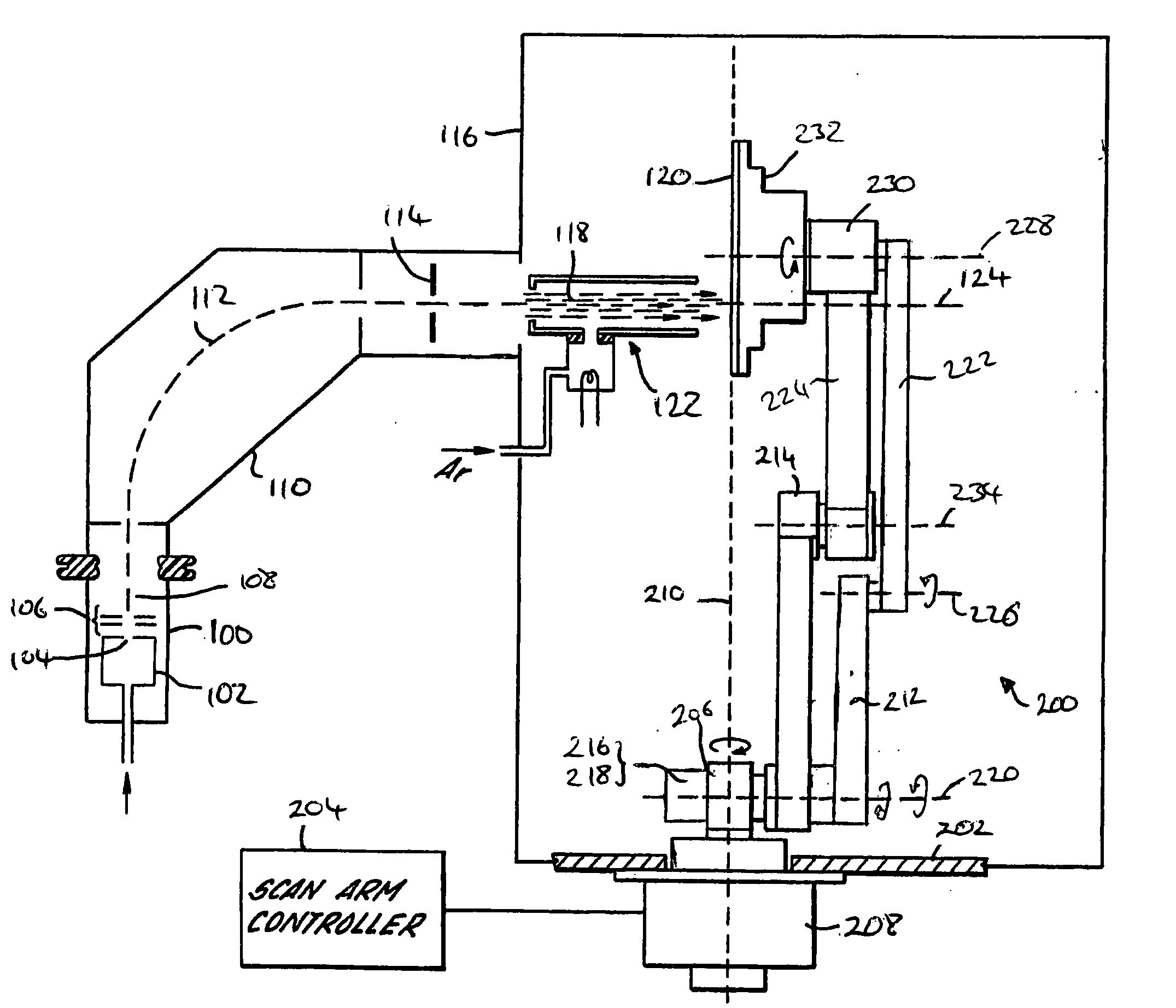
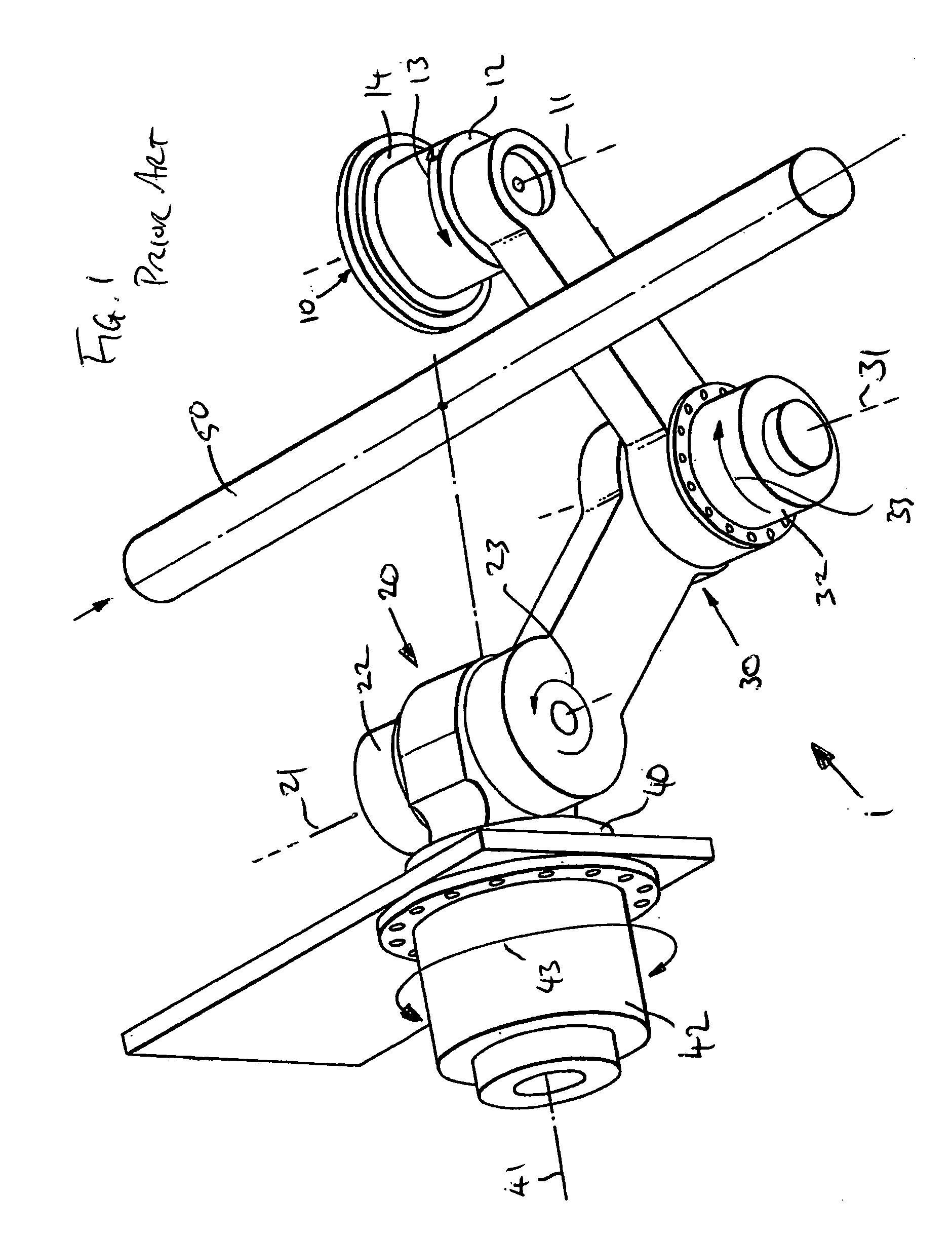
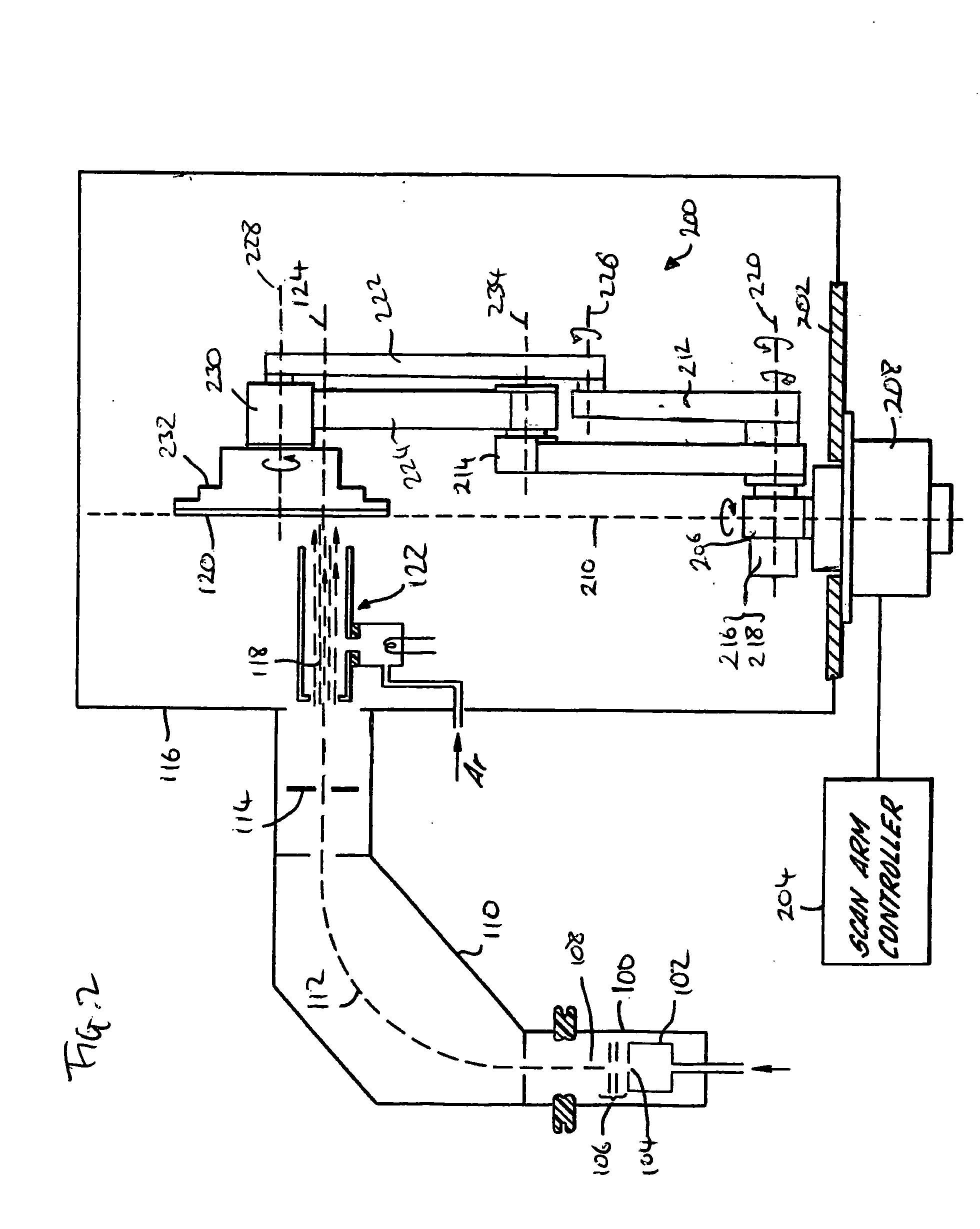
mount the drive means at the axis of rotation, thereby avoiding the need for gears, chains, belts, etc. In WO2004 / 001789 a motor is positioned at the second axis of rotation, and so the
mass of the motor is cantilevered on the first drive arm. As a result, the scanning arm is more prone to vibration and a large torque must be applied to the first drive arm to cause rotation. In the present invention, drive means may be positioned at the fixed first and second axes such that their
mass is not supported by either drive arm. Thus the
inertia of the
scanner is much reduced. Furthermore, the
mass of the scanning arm can be reduced to minimise vibrations, and the mass of the drive means need not be moved.
[0013]Preferably, the first and second axes are parallel. Optionally, the first and second drive arms are coupled to a support such that the first and second axes are coaxial. For example, the first and second drive arms may be mounted to the support on rotary joints that are disposed side by side. The first and second drive arms may then rotate next to each other. Advantageously, the support is adapted to be mounted to a chamber wall of the ion implanter. The first and second drive arms may be coupled to the support adjacent the chamber wall. This is to the benefit of space and also minimizes the torque applied to the chamber wall.
[0014]Optionally, the first and second drive arms are coupled to the support at respective proximal ends. The first and second drive arms may be coupled to the linkage at respective distal ends.
[0015]The linkage may take one of several forms. For example, the linkage may use rotation or translation to effect movement of the substrate holder. As such, the linkage may by a bar arranged to slide as the first and second drive arms, for example through the provision of projecting parts received within guide slots. The guide slots may be provided on the linkage and the projecting parts on the drive arms, or vice versa. Alternatively, one or more rotary joints may be used to couple the linkage to the first and second drive arms.
[0016]The linkage may comprise more than one part. Where more than one part is used, movement may be effected exclusively using rotation. Preferably, the linkage comprises first and second members rotatably coupled together to rotate about a third axis, the first member also being rotatably coupled to the first drive arm to rotate about a fourth axis and the second member also being rotatably coupled to the second drive arm to rotate about a fifth axis. Advantageously, the first axis, second axis, third axis, fourth axis and fifth axis may be arranged to be parallel. Where the first and second axes are coaxial, the first and second drive arms and the first and second members of the linkage form a
quadrilateral. As will be readily apparent, rotating the first and / or second drive arms causes rotation of the first and second members thereby moving the substrate holder.
[0017]Ends of the first and second members may be coupled to the first and second drive arms respectively and, optionally, further ends of the first and second members are coupled to each other. The first member may be provided with the substrate holder. The substrate holder may be provided at the at the end of the first member. This may be the end where it is coupled to the second member. Alternatively, the first member may extend beyond the point where it couples to the second member, and the substrate holder may then be provided at the end of the first member.

