
Process for producing carbon-cladded composite bipolar plates for fuel cells

a carbon-clad composite and fuel cell technology, applied in the field of carbon-cladded composite (ccc), can solve the problems of bipolar plate, one of the most costly components of the pem fuel cell, and known to significantly impact the performance, durability, and cost of the fuel cell system

Inactive Publication Date: 2008-06-26
NANOTEK INSTR GRP LLC
View PDF12 Cites 61 Cited by
  • Summary
  • Abstract
  • Description
  • Claims
  • Application Information

AI Technical Summary

Benefits of technology

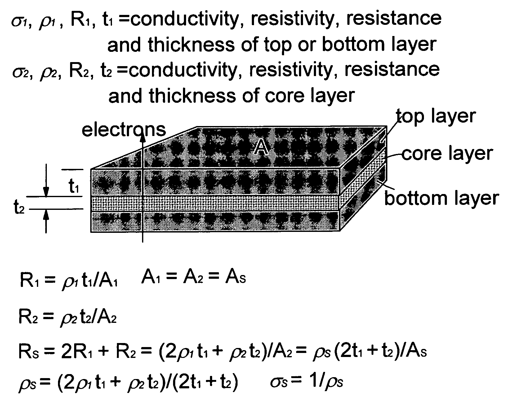
[0023]The core composite layer comprises a conductive filler present in a sufficient quantity to render the core layer electrically conductive with a bulk conductivity of the filler-resin mixture (after curing) no less than 1 S / cm (preferably no less than 10 S / cm). The resulting three-layer carbon-cladded composite composition (after resin curing or molding) has a conductivity typically above 100 S / cm or an areal conductivity greater than 200 S / cm2; which are US Department of Energy (DOE) target conductivity values for composite bipolar plates intended for use in vehicular fuel cells.

Problems solved by technology

The bipolar plate is known to significantly impact the performance, durability, and cost of a fuel cell system.
The bipolar plate, which is typically machined from graphite, is one of the most costly components in a PEM fuel cell.
These methods of fabrication place significant restrictions on the minimum achievable fuel cell thickness due to the machining process, plate permeability, and required mechanical properties.
Further, such plates are expensive due to high machining costs.
The machining of channels into the graphite plate surfaces causes significant tool wear and requires significant processing times.
It is often difficult and time-consuming to properly position and align the separator and stencil layers.
Die-cutting of stencil layers require a minimum layer thickness, which limits the extent to which fuel cell stack thickness can be reduced.
Such laminated fluid flow field assemblies tend to have higher manufacturing costs than integrated plates, due to the number of manufacturing steps associated with forming and consolidating the separate layers.
They are also prone to delamination due to poor interfacial adhesion and vastly different coefficients of thermal expansion between a stencil layer (typically a metal) and a separator layer.
Because most polymers have extremely low electronic conductivity, excessive conductive fillers have to be incorporated, resulting in an extremely high viscosity of the filled polymer melt or liquid resin and, hence, making it very difficult to process.
It is well-known that CVI is a very time-consuming and energy-intensive process and the resulting carbon / carbon composite, although exhibiting a high electrical conductivity, is very expensive.
Clearly, this is also a tedious process which is not amenable to mass production.
Although highly conductive, flexible graphite sheets by themselves do not have sufficient stiffness and must be supported by a core layer or impregnated with a resin.
These FG-metal-FG laminates are also subject to the delamination or blistering problem, which could weaken the plate and may make it more fluid permeable.
Delamination or blistering can also cause surface defects that may affect the flow channels on the plate.
These problems may be difficult to detect during fabrication and may only emerge at a later date.
In particular, thermal cycling between frozen and thawed conditions as are likely to be encountered in an automobile application of the fuel cell, often results in delamination between a flexible graphite layer and the metal layer.
The step of adding ceramic fibers significantly increases the process complexity and cost.
However, commercially available FG sheets can be expensive.
Unfortunately, it is the thickness-direction conductivity of a FG-based SMC that is important for a bipolar plate, rather than the in-plane conductivity.
However, such a composite composition (containing at least 50% conductive reinforcements) tends to result in a thick or bulky molded structure and, hence, is not suitable for the fabrication of thin bipolar plates.
A high filler proportion also means a high mixture viscosity and can present processing difficulty.
The composite is limited to thermoplastic matrix materials and it requires the use of a thermoset binder to hold the filler particles together first prior to a shape molding operation.

Method used


Image

  • Process for producing carbon-cladded composite bipolar plates for fuel cells
  • Process for producing carbon-cladded composite bipolar plates for fuel cells
  • Process for producing carbon-cladded composite bipolar plates for fuel cells

Examples


Embodiment Construction

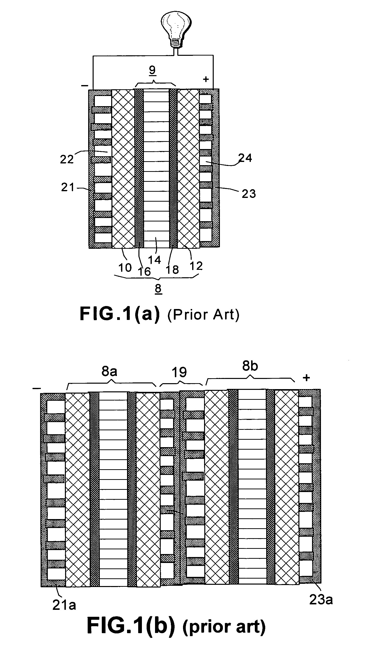
[0033]A prior art fuel cell, as shown in FIG. 1(a), typically comprises a membrane electrode assembly 8, which comprises a proton exchange membrane 14 (PEM), an anode backing layer 10 connected to one face of the PEM 14, and a cathode backing layer 12 connected to the opposite face of PEM 14. Anode backing layer 10 is also referred to as a fluid diffusion layer or diffuser, typically made of carbon paper or carbon cloth. A platinum / ruthenium electro-catalytic film 16 is positioned at the interface between the anode backing layer and PEM 14 for promoting oxidation of the methanol fuel. Similarly, at the cathode side, there are a backing layer or diffuser 12 (e.g., carbon paper or carbon cloth) and a platinum electro-catalytic film 18 positioned at the interface between the cathode backing layer and PEM 14 for promoting reduction of the oxidant.

[0034]In practice, the proton exchange membrane in a PEM-based fuel cell is typically coated on both sides with a catalyst (e.g., Pt / Ru or Pt)...


PUM

PropertyMeasurementUnit
thicknessaaaaaaaaaa
thicknessaaaaaaaaaa
areal conductivityaaaaaaaaaa

Abstract

The present invention provides a process for making a carbon-cladded composite composition for use as a fuel cell flow field plate or bipolar plate. In one preferred embodiment, the process comprises (a) providing a layer of conductive filler-resin composite having a first and a second primary surface; (b) depositing two clad layers of conductive carbon or graphite material onto the two primary surfaces, respectively, to produce a clad-composite-clad (three-layer) precursor structure; (c) creating flow field channels on the two primary exterior surfaces of the three-layer precursor; and (d) curing or solidifying the resin to form the desired bipolar plate. These steps are preferably integrated into a continuous roll-to-roll process for the mass production of bipolar plates. The conductive carbon or graphite material preferably comprises particles selected from the group consisting of carbon fibers, carbon nano-tubes, graphitic nano-fibers, nano-scaled graphene plates, carbon blacks, fine graphite powder, and combinations thereof.

Description

[0001]The present invention is based on the research results of a project supported by the DOE SBIR Program. The US government has certain rights on this invention.FIELD OF THE INVENTION[0002]The present invention relates to a carbon-cladded composite (CCC) for use as a fuel cell bipolar plate or flow field plate. In particular, it relates to a highly conductive carbon- or graphite-faced polymer matrix composite structure for use as a flow field plate or bipolar plate in a proton exchange membrane fuel cell.BACKGROUND OF THE INVENTION[0003]A fuel cell converts chemical energy into electrical energy and some thermal energy by means of a chemical reaction between a fuel (e.g., hydrogen gas or a hydrogen-containing fluid) and an oxidant (e.g., oxygen or air). A proton exchange membrane (PEM) fuel cell uses hydrogen or hydrogen-rich reformed gases as the fuel, a direct-methanol fuel cell (DMFC) uses methanol-water solution as the fuel, and a direct ethanol fuel cell (DEFC) uses ethanol-...

Claims


Application Information

Patent Timeline
Patent Type & Authority Applications(United States)
IPC IPC(8): H01B1/06
CPCH01B1/122H01M8/0213H01M8/0221Y02E60/50H01M8/0228H01M8/0258H01M2008/1095H01M8/0226H01M8/0267Y02P70/50
Inventor JANG, BOR Z.ZHAMU, ARUNAGUO, JIUSHENG
Owner NANOTEK INSTR GRP LLC
Learn More