Remediation of waste water

a technology of waste water and remediation, applied in the direction of water/sewage multi-stage treatment, other chemical processes, separation processes, etc., can solve the problems of reducing the flow of waste water, clogging and possible overflow, and posing a risk to public health, so as to promote the remediation of waste water, enhance the removal of contaminants, and promote the effect of removing contaminants

Active Publication Date: 2008-07-17
LIFT EASY OF AMERICA LLC (US)
View PDF6 Cites 10 Cited by
  • Summary
  • Abstract
  • Description
  • Claims
  • Application Information

AI Technical Summary

Benefits of technology

[0017]Further, a method for promoting the removal of contaminants from waste water is provided by adding the non-toxic composition to the waste water, wherein the composition enhances removal of the contaminants by bacteria in the waste water.
[0019]The compositions and methods described above effectively promote the dispersion of agglomerated FOG particles, resulting in much more efficient remediation of FOG and other contaminants in the waste water.

Problems solved by technology
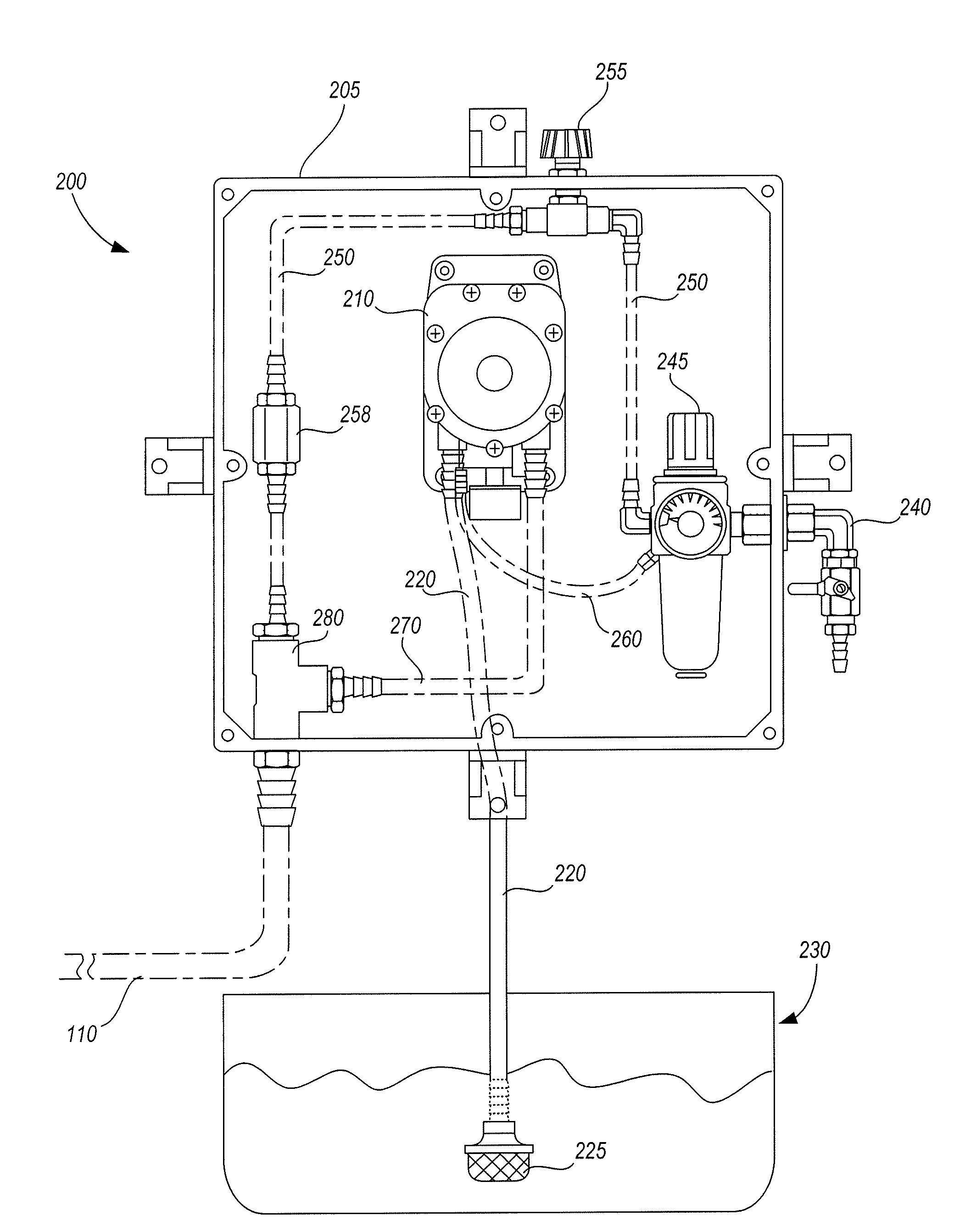
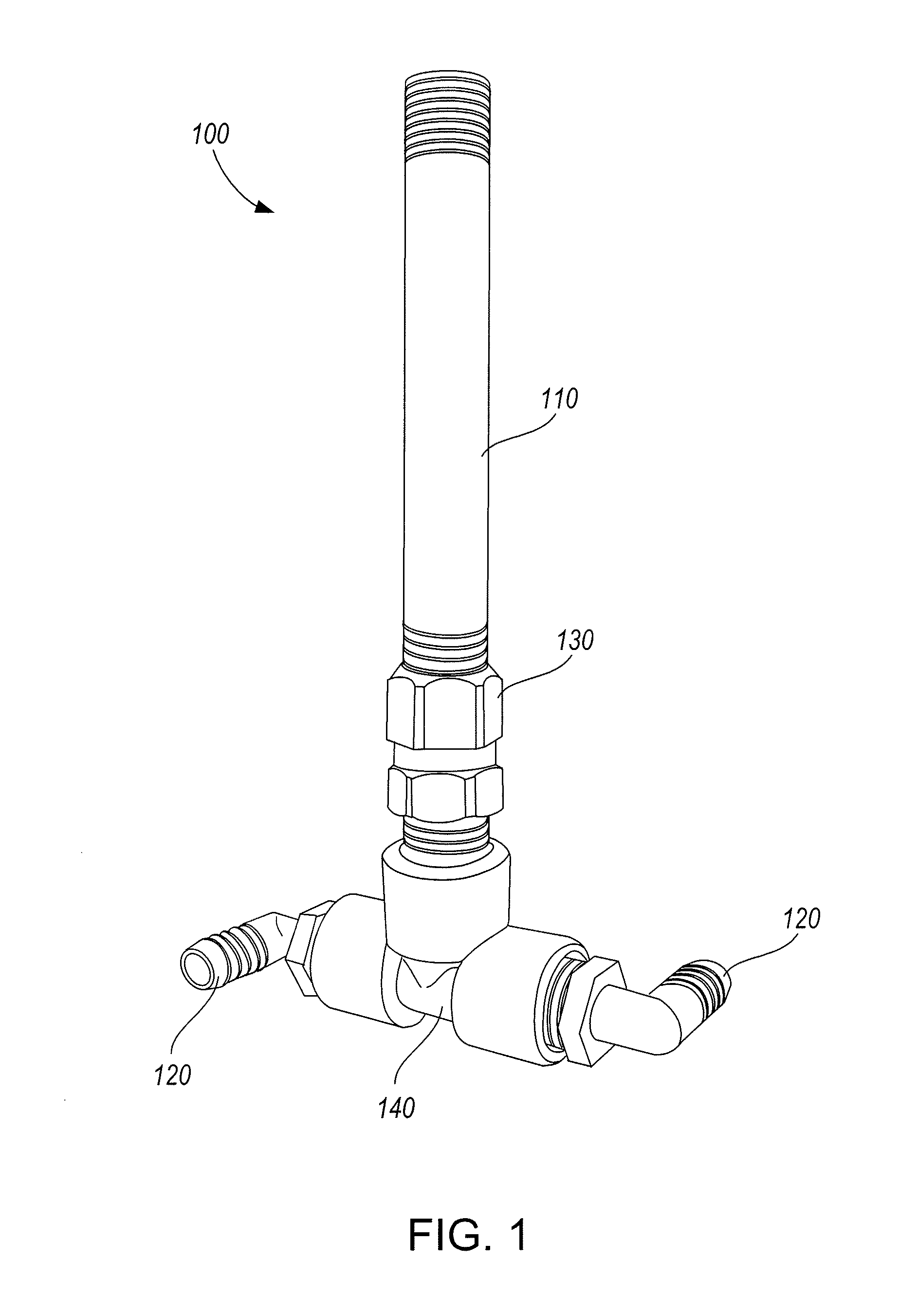
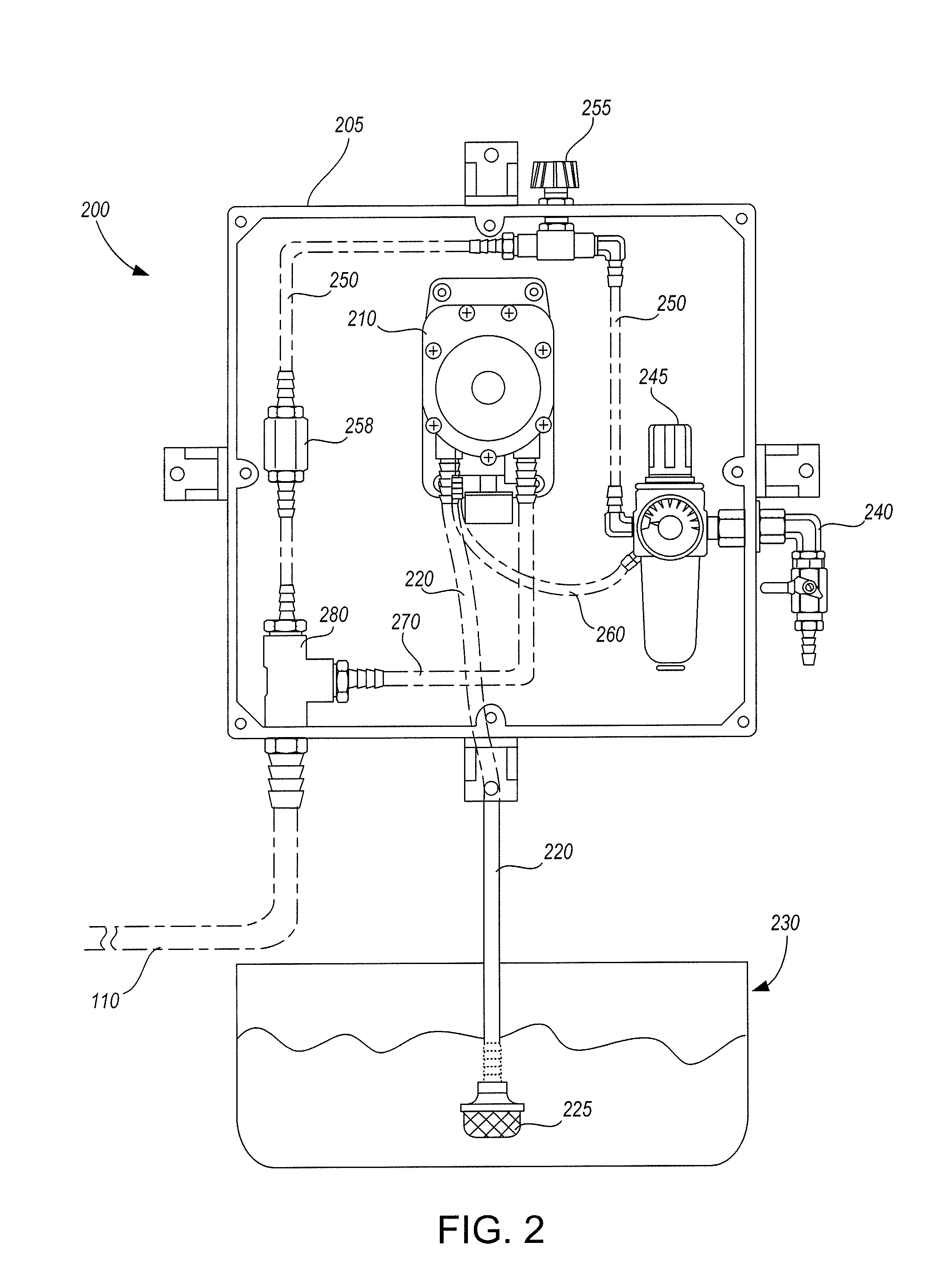
Waste water generally contains contaminants such as fat, oil, grease, heavy metals, and other organic and inorganic substances at levels considered hazardous to the environment and which could pose a risk to public health.
In addition, these contaminants build up on septic and sewer system components such as pipes, grinder pumps, lift stations and holding tanks, causing clogging and possible overflow of these systems, decreased waste water flow, and increased wear on system components.
Moreover, when contaminants such as fat, oil and grease (“FOG”) are introduced into a grease trap, septic tank or waste water treatment plant, or low-flow areas of sewer systems, they have a tendency to coagulate into larger FOG particles.
These larger FOG particles, with a reduced overall surface area as compared to an equal mass of smaller FOG particles, are not treated as efficiently by the bacteria in the septic tank and waste water treatment plant.
As a result, remediation efficiency of these systems is substantially degraded.
Prior chemical-based waste water treatment compositions, systems or methods have been only partially effective at preventing or treating the problems described above.
Prior chemical treatments have been effective in breaking up FOG particles, but have left residual chemical compounds that either adversely affect operation of the grease trap, septic tank or waste water treatment system, or include additional contaminants which must be removed prior to discharging the treated water into effluent water streams.
Moreover, treatments that simply dislodge FOG from the grease trap, septic tank, and sewer systems without physically breaking up the FOG particles can result in clogs or overflows of these systems as the FOG particles recombine downstream.

Method used


Image

  • Remediation of waste water
  • Remediation of waste water
  • Remediation of waste water

Examples


example 1

[0067]A composition having about 54% by weight of T-Tergamide 1CD, about 13% by weight of Tergitol NP-9, about 13% by weight of T DET A 826 and about 20% by weight of Amphosol 2CSF was prepared by mixing T-Tergamide 1 CD, Tergitol NP-9 and T DET A 826, and then slowly adding Amphosol 2CSF to this mixture. Approximately 1.25 gallons of this composition was diluted in a 55-gallon drum with 53.75 gallons of water, such that the concentration of the composition in the drum was approximately 2%.

example 2

[0068]A lift station approximately 12 feet by 30 feet in size, with a volume of 1.5 million gallons a day, had a 12-inch cake of grease and other solids covering its entire surface, corresponding to a volume of approximately 360 cubic feet of grease and solids. The lift had very low velocity and almost no turbulence of the contents. When the lift was pumped down, a “shoe” of grease extended from the wall approximately 12 inches around the perimeter at the high water mark. Floats and other equipment in the station were covered with grease. Due to the design of the pumps, they required 3 feet of head above their top, and as a result a complete pump-down to rid the lift of loosened FOG, solids and accumulated latex was not possible. Strong odors in the vicinity of the lift station resulted in numerous complaints from nearby residents.

[0069]The composition of Example 1 was applied approximately daily for a 28-day trial period, first at a hatch at the outflow end of the lift and then, wh...

example 3

[0071]A lift with a diameter of approximately 5 feet and a volume of 2 million gallons a day had a 39-inch cake-covered well, corresponding to a volume of approximately 64 cubic feet of grease and solids. Three high-velocity lines with 8 inch diameters entered the lift at varying heights, providing for turbulent flow. The station had grease accumulation on the walls, ladder, float switches, and other station components, as well as a “shoe” around the perimeter of the lift.

[0072]The composition of Example 1 was applied directly to the cake approximately daily for a 29-day trial period. For the first 10 days approximately 20 gallons of the diluted composition of Example 1 were applied daily, for the next 9 days approximately 15 gallons a day were applied, and for the final 10 days approximately 5 gallons a day were applied.

[0073]Within five days of beginning the trial, the cake was nearly gone. No odors were detected at the station other than a slight, non-offensive, “dirty dish water...


PUM

PropertyMeasurementUnit
surface areaaaaaaaaaaa
pressureaaaaaaaaaa
pressureaaaaaaaaaa

Abstract

A non-toxic waste water treatment composition is provided. The waste water treatment composition is formed from: (a) an alkanolamide; (b) an ethoxylated alkylphenol, ethoxylated aryl phenol, or combination thereof, (c) a first surfactant selected from the group consisting of: an ethoxylated alcohol, a glycerol ester, a propoxylated fatty acid, an ethoxylated fatty acid, a propoxylated alcohol, an ethoxylated alcohol, a propoxylated alkyl phenol, an ethoxylated alkyl phenol, and a combination thereof, (d) a second surfactant selected from the group consisting of: a sulfosuccinate, a sulfosuccinate derivative, an imidazoline, an imidazoline derivative, and a combination thereof, and (e) optionally, a foaming agent. Methods for forming the non-toxic composition and for treating waste water with the composition are also provided. Finally an apparatus for introducing a waste water treatment composition into a waste water system is provided. The apparatus includes tubing for delivering the waste water treatment composition to at least one spray nozzle and a swivel fitting connecting the tubing to the spray nozzle. The spray nozzle is configured to deliver the waste water treatment composition into the waste water system, and the swivel fitting permits 360 degree rotation of the spray nozzle around the tubing.

Description

CROSS-REFERENCE TO RELATED APPLICATION[0001]This application claims priority to U.S. provisional application Ser. No. 60 / 884,717 filed on Jan. 12, 2007, the contents of which are incorporated by reference herein in its entirety.FIELD OF THE INVENTION[0002]This invention relates to non-toxic compositions and associated methods for enhancing the remediation of waste water.BACKGROUND OF THE INVENTION[0003]Waste water generally contains contaminants such as fat, oil, grease, heavy metals, and other organic and inorganic substances at levels considered hazardous to the environment and which could pose a risk to public health. In addition, these contaminants build up on septic and sewer system components such as pipes, grinder pumps, lift stations and holding tanks, causing clogging and possible overflow of these systems, decreased waste water flow, and increased wear on system components.[0004]Moreover, when contaminants such as fat, oil and grease (“FOG”) are introduced into a grease tr...

Claims


Application Information

Patent Timeline
Patent Type & Authority Applications(United States)
IPC IPC(8): C02F9/04C09K3/32
CPCC02F1/686
Inventor SPARKS, JORDANVIS, DAVID
Owner LIFT EASY OF AMERICA LLC (US)
Why Eureka
Try Eureka