High power optical apparatus employing large-mode-area, multimode, gain-producing optical fibers

a high-power, multi-mode technology, applied in the direction of optics, optical elements, instruments, etc., can solve the problems of limited power, limited mfa, limited silica concentration, etc., and achieve the effects of reducing the length of the fiber, reducing the amount of mfa, and high pump absorption and gain

Active Publication Date: 2008-07-31
OFS FITEL LLC
View PDF12 Cites 95 Cited by
  • Summary
  • Abstract
  • Description
  • Claims
  • Application Information

AI Technical Summary

Benefits of technology

[0010]To achieve high pump absorption and gain per unit length, we utilize a multimode GPF that is core-pumped with a high brightness pump source. The core pumping scheme has the advantage that, in a preferred embodiment, the pump light and signal light propagate in essentially the same transverse mode and, therefore, essentially perfectly overlap one another, which reduces ASE. Nearly perfect overlap also minimizes the fiber length needed for a particular gain, which is important to reduce impairments caused by nonlinear effects such as Raman scattering, Brillouin scattering and self-phase modulation.
[0011]In order to generate and deliver high power pulses (e.g., >10 s of kW of peak power), preferably our GPF has a relatively high core area, which is advantageous in increasing the energy storage capacity of the fiber (and hence the pulse energy) and in decreasing the effect of nonlinearities, which reduces pulse degradation.

Problems solved by technology

However, Er concentration in silica is limited by pair-induced quenching.
However, the Taverner amplifier design is disadvantageous for several reasons: (i) it uses multiple bulk optical components, which are difficult to align and to keep aligned as environmental conditions change with time; (ii) it uses a Ti-sapphire solid state pump laser, which is large, difficult to control, and has limited power; and (iii) it uses a single mode Er-doped fiber, which means that the MFA is limited and hence the energy storage capacity of the fiber is likewise limited.

Method used


Image

  • High power optical apparatus employing large-mode-area, multimode, gain-producing optical fibers
  • High power optical apparatus employing large-mode-area, multimode, gain-producing optical fibers
  • High power optical apparatus employing large-mode-area, multimode, gain-producing optical fibers

Examples


example

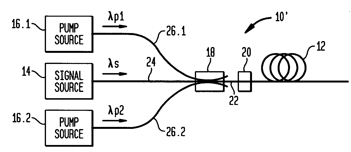
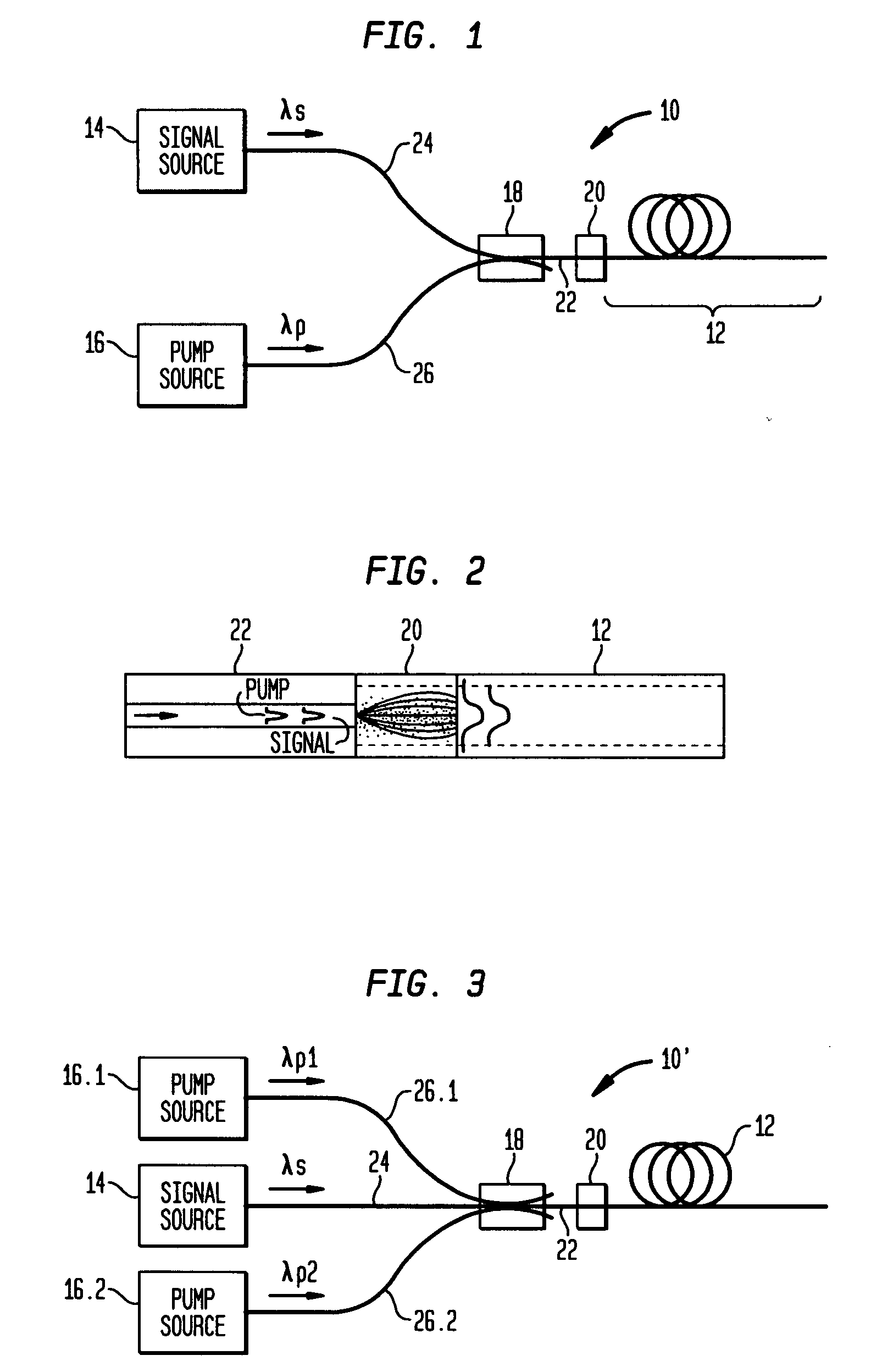
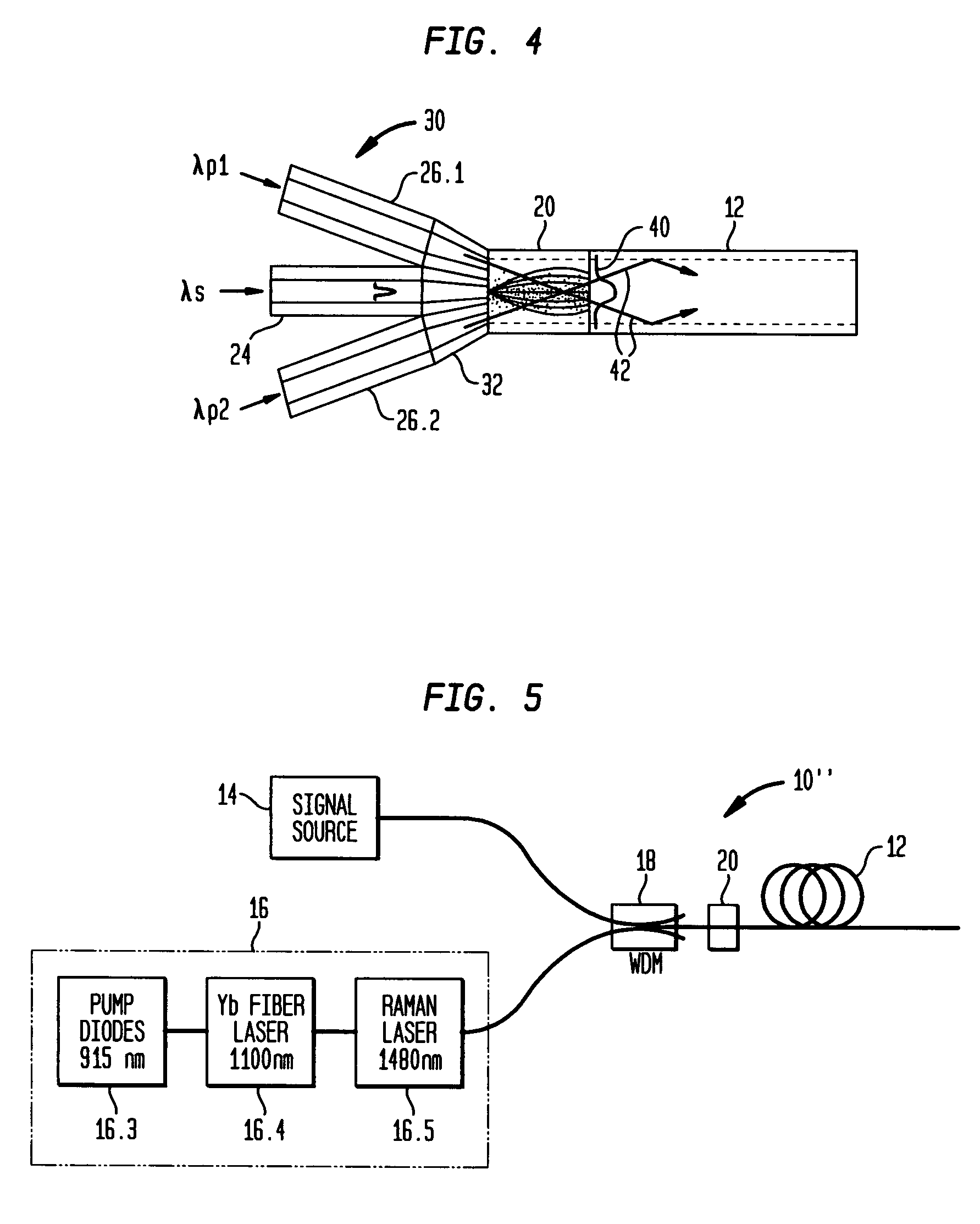
[0053]This example describes amplification of nanosecond pulses in a single-clad, multimode, LMA Er-doped fiber. Various materials, dimensions and operating conditions are provided by way of illustration only and, unless otherwise expressly stated, are not intended to limit the scope of the invention. The area of the Er-doped core was a record 875 μm2. The core was pumped at 1480 nm with a Raman fiber laser. The large energy storage capacity and low nonlinearity of the Er-doped fiber enabled an all-fiber system generating record energy per pulse and record peak power in a single transverse mode with an M2<1.1.

[0054]Although the Er-doped LMA fiber was a multimode fiber, the signal and pump light propagated in this fiber in a single (fundamental) mode.

[0055]All-fiber means components are fusion-splice together, without free-space coupling into the fibers. Laser diodes and other components having fiber pigtails may use free space coupling, but inside well-controlled packages.

[0056]FIG....


PUM


Abstract

Optical apparatus includes a multimode, gain-producing fiber for providing gain to signal light propagating in the core of the fiber, and a pump source for providing pump light that is absorbed in the core, characterized in that (i) the pump source illustratively comprises a low brightness array of laser diodes and a converter for increasing the brightness of the pump light, (ii) the pump light is coupled directly into the core, and (iii) the area of the core exceeds approximately 350 μm2. In one embodiment, the signal light propagates in a single mode, and the pump light co-propagates in at least the same, single mode, both in a standard input fiber before entering the gain-producing fiber, and a mode expander is disposed between the input fiber and the gain-producing fiber. In another embodiment, multiple pumps are coupled into the core of the gain-producing fiber. The pumps may generate light of the same wavelength or of different wavelengths. In accordance with a particular embodiment of our invention, we have demonstrated amplification of nanosecond optical pulses at 1545 nm in a single clad Er-doped fiber having a core area of 875 μm2; the core was pumped by a high brightness Raman laser at 1480 nm; and the pulses had a record peak power of several hundred kW.

Description

BACKGROUND OF THE INVENTION[0001]1. Field of the Invention[0002]This invention relates to high power optical apparatus employing large-mode-area (LMA), multimode, gain-producing optical fibers, and, more particularly, to high power optical amplifiers and lasers using such fibers.[0003]2. Discussion of the Related Art[0004]In order to amplify an optical signal propagating in the core of an optical fiber, typically the core is doped with a gain-producing species and then pumped by an optical pump at a wavelength that is absorbed by the species. In silica optical fibers the core is illustratively doped with a rare-earth element (e.g., Er, Yb, Er—Yb, Nd, Tm, Ho, etc) or chromium (Cr), which enables signals at wavelengths in the near infrared range (e.g., ˜1000-1600 nm) to be amplified. Er and Er—Yb silica fibers are commonly used to amplify signals at wavelengths above about 1500 nm and are typically pumped at or near either 980 nm or 1480 nm.[0005]Applications of gain-producing fibers ...

Claims


Application Information

Patent Timeline
Patent Type & Authority Applications(United States)
IPC IPC(8): H01S3/09
CPCG02B6/02019G02B6/2552G02B6/32G02B6/2804G02B6/262
Inventor DIGIOVANNI, DAVID JOHNHEADLEY, CLIFFORD EVERILL
Owner OFS FITEL LLC
Why Eureka
Try Eureka