Fly's Eye Lens Short Focal Length Solar Concentrator

a solar concentrator and fly-eye lens technology, applied in the field of photovoltaics, can solve problems such as reducing cell efficiency, and achieve the effect of efficient and economic heat dissipation from many small pv cell sites

Inactive Publication Date: 2008-08-07
CORIO RONALD P
View PDF10 Cites 88 Cited by
  • Summary
  • Abstract
  • Description
  • Claims
  • Application Information

AI Technical Summary

Benefits of technology

[0012]The solution to the shortcomings of the prior art is to use small lens elements concentrating onto small high-efficiency rear contact solar cells. With small lens elements formed into a sheet, co...

Problems solved by technology

Higher temperatures lead...

Method used


Image

  • Fly's Eye Lens Short Focal Length Solar Concentrator
  • Fly's Eye Lens Short Focal Length Solar Concentrator
  • Fly's Eye Lens Short Focal Length Solar Concentrator

Examples


Embodiment Construction

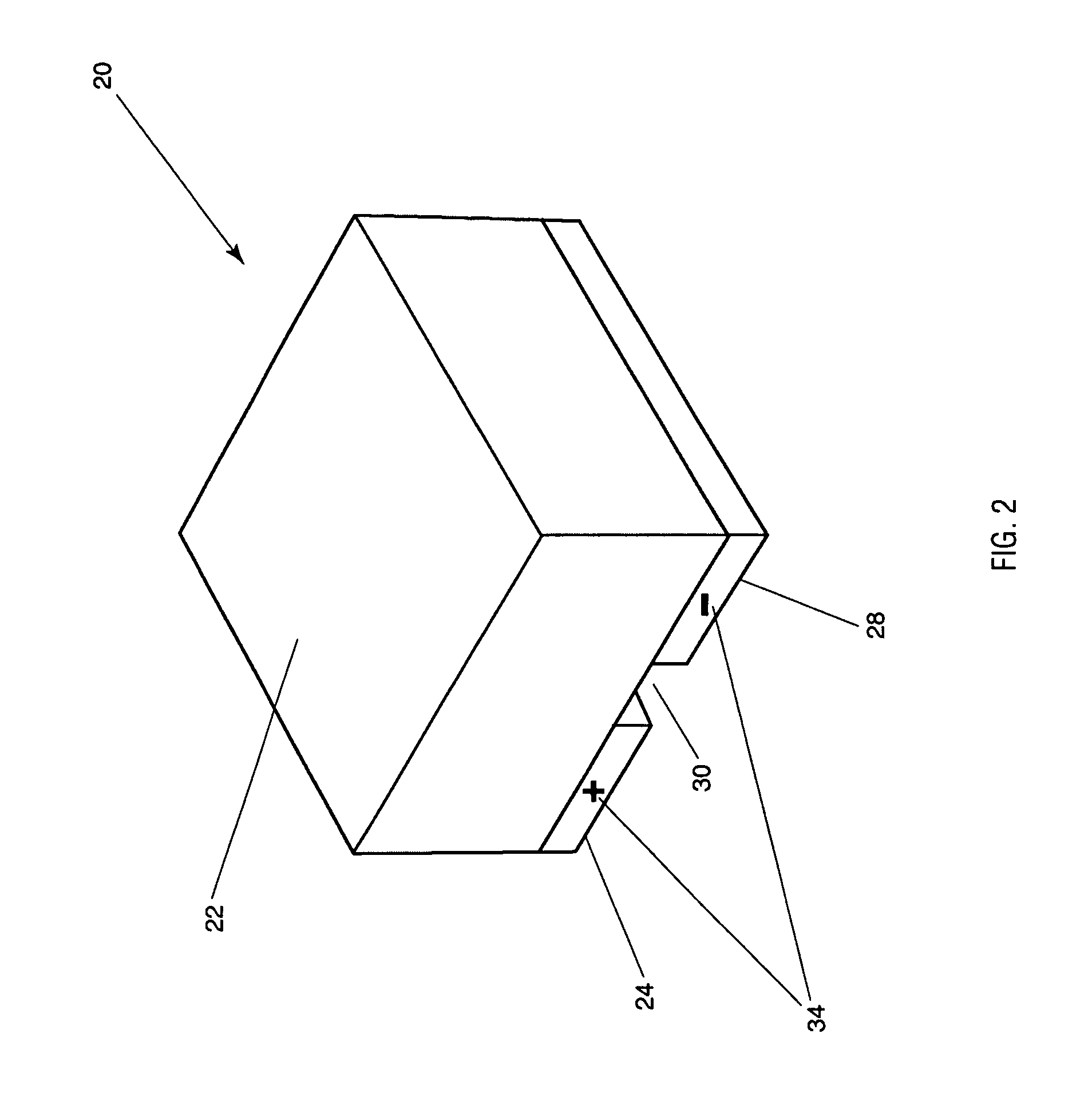
[0032]As shown in FIG. 2, solar cells used in the assembly of one aspect of the present invention are pre-fabricated rectangular or square photovoltaic semiconductor crystal wafers or PV cells 20 having a photoactive top surface 22 and a dual electrode conductive rear surface 34. Each wafer may be approximately 25 millimeters square and fabricated from material such as silicon, known to have photovoltaic properties.

[0033]Bonded both mechanically and electrically to the rear cell conductive surface 34 are two rear conductors, one positive 24 and one negative 28, which are separated by a void 30 in the conductive surface 34 and readily permits the cell to be electrically joined to printed circuit laminate substrate portion of the module.

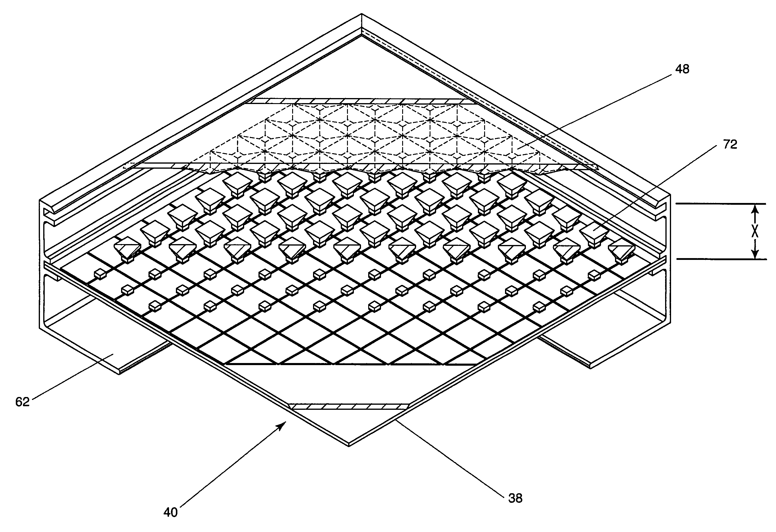
[0034]FIG. 3 shows the receiver sheet assembly of a power module of an aspect of the present invention. Receiver sheet assembly 32 includes a plurality of photovoltaic (PV) cells 20, electrically and mechanically disposed on the top surface of laminate...


PUM

PropertyMeasurementUnit
Timeaaaaaaaaaa
Thicknessaaaaaaaaaa
Lengthaaaaaaaaaa

Abstract

A compact solar concentrator photovoltaic module assembly includes a plurality of rear contact solar cells configured in a matrix array on a substrate. The substrate is comprised of conductors laminated to an insulator sheet to form a receiver sheet. A lens sheet on which many lenses have been formed is disposed in a fixed spaced relation to the substrate and operates to focus sunlight onto the active surfaces of the PV cells. The overall thickness of the concentrator module is less than four inches thick. The receiver sheet may be assembled using standard, surface mount printed circuit board assembly techniques. The receiver sheet may have a secondary optical element and may also serve as part of the encapsulant for environmental protection.

Description

CROSS REFERENCE TO RELATED APPLICATIONS[0001]This application is based on U.S. Provisional Application Ser. No. 60 / 898,989 entitled “Fly's Eye Lens Short Focal Length Solar Concentrator”, filed on Feb. 1, 2007, the teachings of which are incorporated herein by reference.BACKGROUND OF THE INVENTION[0002]1. Field of the Invention (Technical Field)[0003]The present invention relates to photovoltaics (PV) and more specifically to concentrator photovoltaic modules and methods for making same.[0004]2. Background Art[0005]Photovoltaic cells were first developed in the 1950's and successfully deployed in space applications. Since PV's success in space, terrestrial applications for PV have been steadily increasing. Initial applications for terrestrial PV were in remote areas where traditional sources of energy were not feasible. The terrestrial PV market was relatively small, mostly due to the relatively high cost of PV modules and systems. In the last 5 years there has been large growth in ...

Claims


Application Information

Patent Timeline
IPC IPC(8): H01L31/052H05K3/34
CPCH01L31/042H01L31/048H05K3/341Y10T29/49144H01L31/0516H01L31/0543Y02E10/52H01L31/052
Inventor CORIO, RONALD P.
Owner CORIO RONALD P
Why Eureka
Try Eureka