Specimen inspection stage implemented with processing stage coupling mechanism

Inactive Publication Date: 2008-08-21
ELECTRO SCI IND INC
View PDF17 Cites 10 Cited by
  • Summary
  • Abstract
  • Description
  • Claims
  • Application Information

AI Technical Summary

Benefits of technology

[0013]When laser processing of the specimen is complete, the result is inspected, typically under a high-power microscope outfitted with a camera. On-board inspections maximize efficiency of both production and process development activities. Furthermore, there is a significant stability advantage in supporting the inspection equipment, which is made massive by heavy zoom lenses, on the same rigid substrate that supports the lighter weight processing equipment. Instead of mounting heavy inspection equipment on the

Problems solved by technology

In the case in which the laser beam position is continually adjusted, state-of-the-art structures supporting the laser assembly are too flexible to maintain the required level of precision.
Moreover, as circuit dimensions shrink, particle contamination becomes of greater conc

Method used


Image

  • Specimen inspection stage implemented with processing stage coupling mechanism
  • Specimen inspection stage implemented with processing stage coupling mechanism
  • Specimen inspection stage implemented with processing stage coupling mechanism

Examples


Embodiment Construction

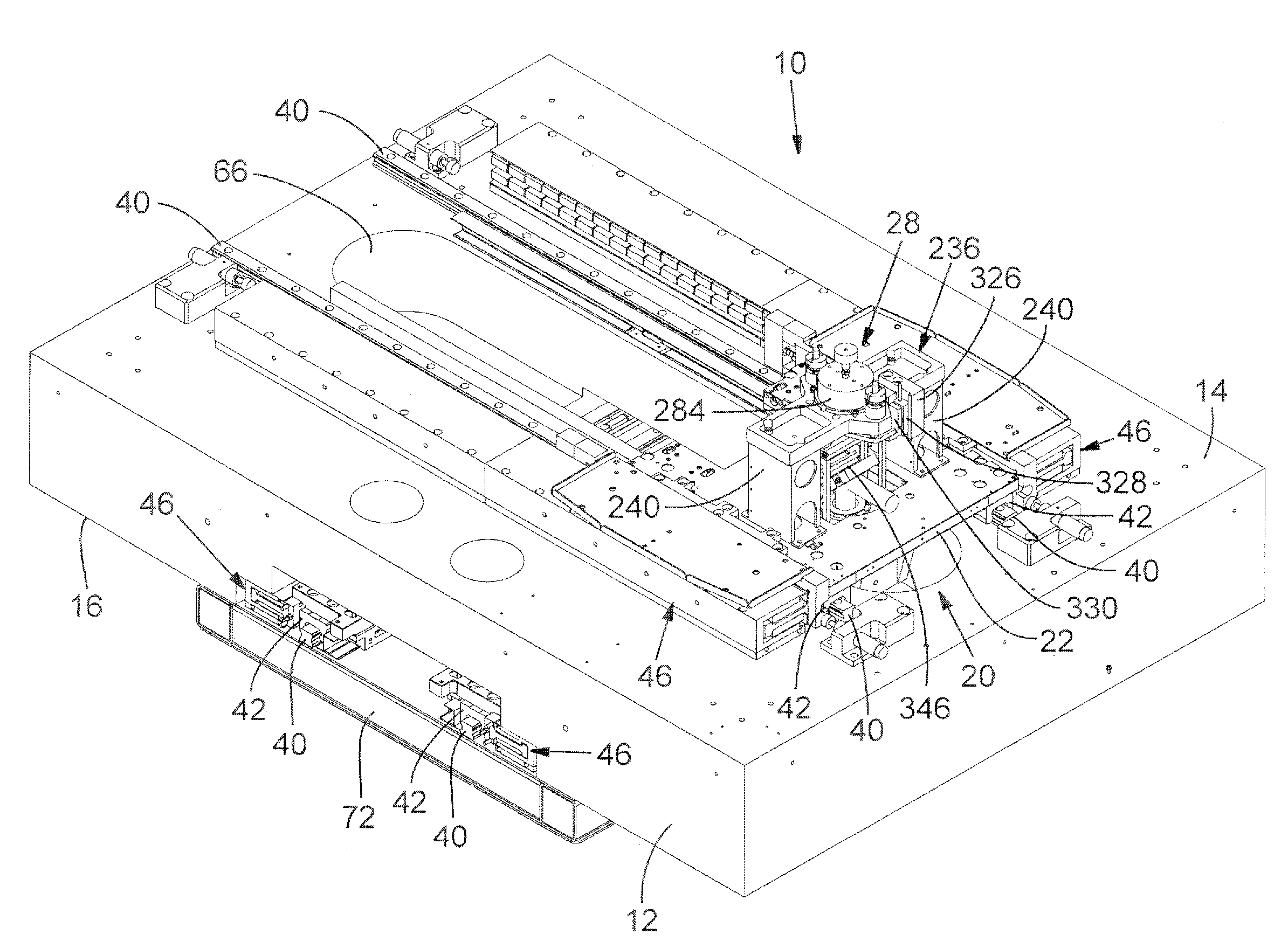
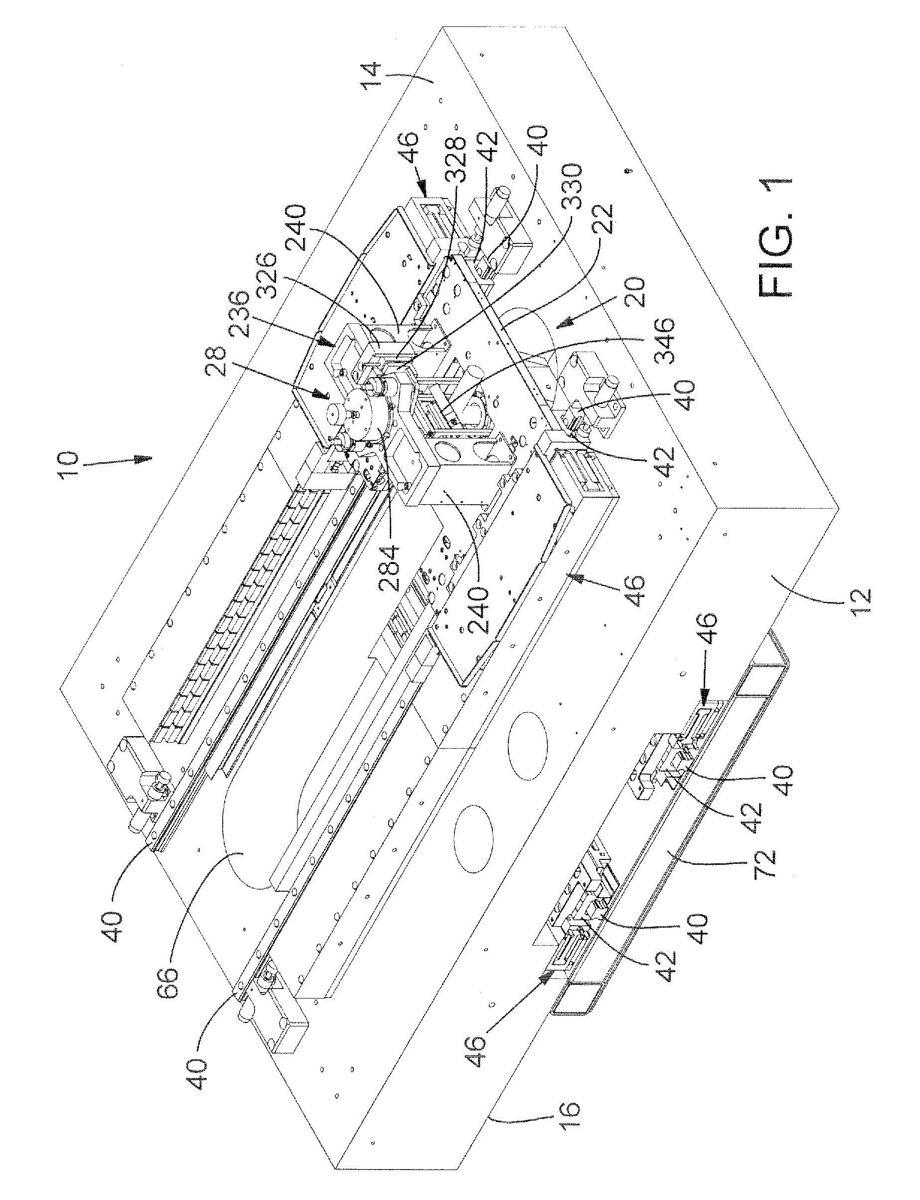
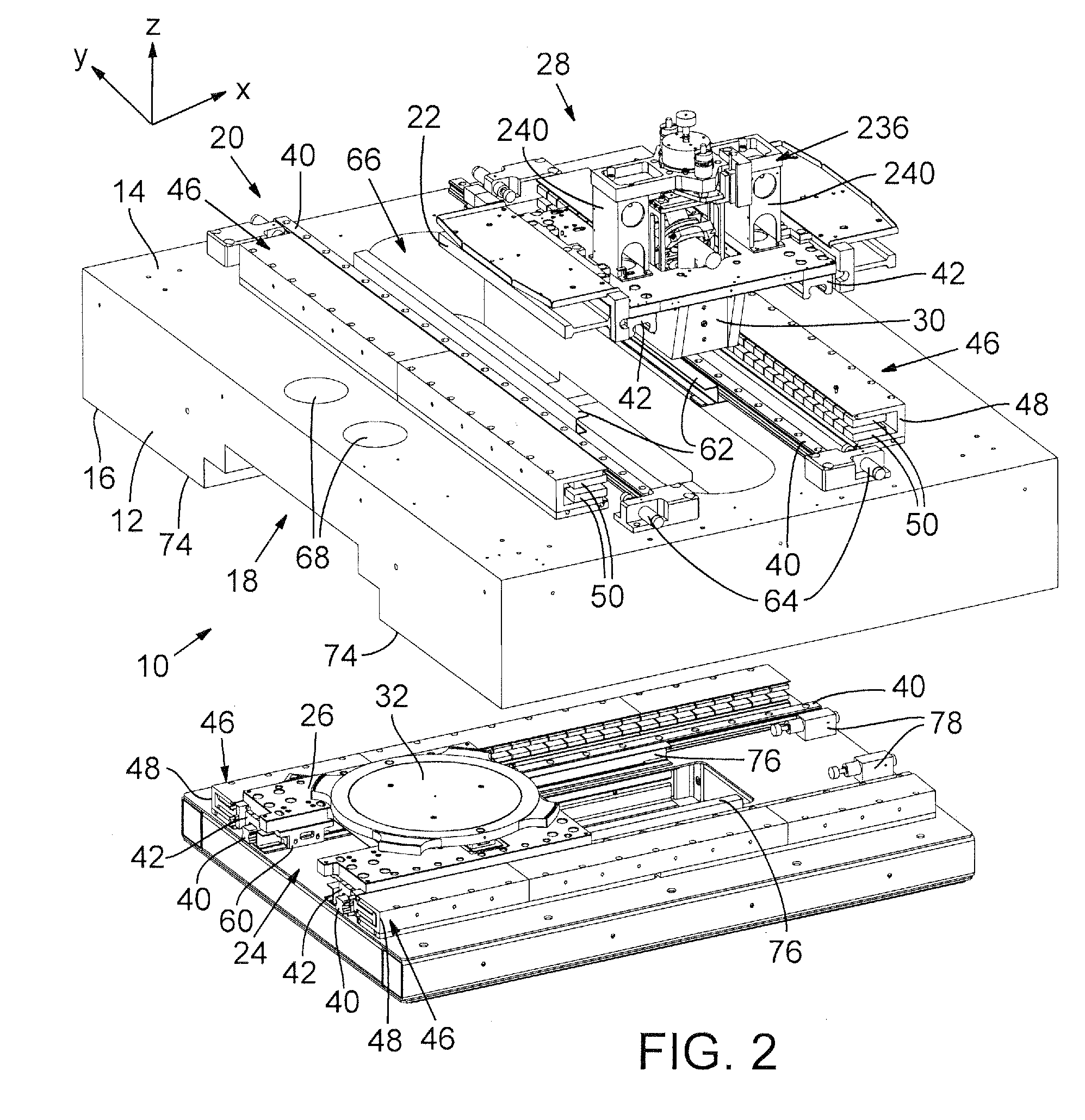
[0024]FIGS. 1 and 2 show a decoupled, multiple stage positioning system 10, which, in a preferred embodiment, supports components of a laser processing system through which a laser beam propagates for incidence on a target specimen. Positioning system 10 includes a dimensionally stable substrate 12 made of a stone slab, preferably formed of granite, or a slab of ceramic material, cast iron, or polymer composite material such as Anocast™. Substrate 12 has a first or upper flat major surface 14 and a second or lower flat major surface 16 that has a stepped recess 18. Major surfaces 14 and 16 include surface portions that are plane parallel to each other and conditioned to exhibit flatness and parallelism within about a ten micron tolerance.

[0025]A surface portion of upper major surface 14 and a first guide track assembly 20 are coupled to guide movement of a laser optics assembly stage 22 along a first axis, and a surface portion of lower major surface 16 and a second guide track asse...


PUM

PropertyMeasurementUnit
Massaaaaaaaaaa

Abstract

A specimen inspection stage implemented with a processing stage coupling mechanism provides a capability to conduct with maximum efficiency post-processing specimen inspections on-board a processing platform. Heavy inspection equipment is mounted on a specimen inspection stage that is separate from a processing stage. In a preferred embodiment, the processing stage moves in response to an applied motive force and performs laser-based processing operations on a specimen. While laser processing is ongoing, the specimen inspection stage remains parked in its home position. When it is time for post-processing inspection, a stage coupling and decoupling mechanism couples together the specimen inspection stage and the processing stage, which transports the specimen inspection stage to and from the specimen position.

Description

RELATED APPLICATIONS [0001]This is a continuation-in-part of U.S. patent application Ser. No. 11 / 676,937, filed on Feb. 20, 2007, and claims benefit of U.S. Provisional Patent Application No. 60 / 890,807, filed Feb. 20, 2007.COPYRIGHT NOTICE [0002]©2007 Electro Scientific Industries, Inc. A portion of the disclosure of this patent document contains material that is subject to copyright protection. The copyright owner has no objection to the facsimile reproduction by anyone of the patent document or the patent disclosure, as it appears in the Patent and Trademark Office patent file or records, but otherwise reserves all copyright rights whatsoever. 37 CFR §1.71(d).TECHNICAL FIELD [0003]The present disclosure relates to specimen processing systems and, in particular, to achieving operational efficiency in performing specimen processing and inspection.BACKGROUND INFORMATION [0004]Wafer transport systems configured for use in semiconductor wafer-level processing typically include a stage...

Claims


Application Information

Patent Timeline
IPC IPC(8): G01N21/01
CPCB23K26/0853B23K26/032H01L22/00
Inventor KOSMOWSKI, MARK T.FERGUSON, ROBERTWILLEY, JEREMY
Owner ELECTRO SCI IND INC
Why Eureka
Try Eureka