Magnetic Bead Trap and Mass Spectrometer Interface

a technology of mass spectrometer and magnet bead trap, which is applied in the direction of separation process, laboratory glassware, centrifuge, etc., can solve the problems of reducing analytical precision and sensitivity, waste of sample peptides, and adsorption mechanism of low abundance peptides, so as to minimize losses on surfaces encountered, the effect of rapid introduction of analytes

Inactive Publication Date: 2008-09-11
ANDERSON FORSCHUNG GROUP
View PDF4 Cites 49 Cited by
  • Summary
  • Abstract
  • Description
  • Claims
  • Application Information

AI Technical Summary

Benefits of technology

[0011]The invention makes possible the rapid introduction of analytes on magnetic bead capture supports into capillary and other flow systems, and thus allows high-throughput processing of such samples on expensive MS instrumentation. The invention provides a general approach to handling analytes that minimizes losses on surfaces encountered between the initial capture step and final delivery into an analytical system.

Problems solved by technology

When very small amounts of analytes are involved, this presents a major challenge, since small amounts of many substances can be bound by (and therefore lost upon) the surfaces of storage vessels, transporting devices, connecting tubing, etc.
LC-MS / MS autosamplers used in the most sensitive nanoflow chromatography systems typically cannot access the last small volume of sample in such vessels, leading to wasted sample peptides.
In addition, exposure of low-abundance peptides to the large wall surface area of multiwell plate wells and sample vials often results in substantial adsorptive losses, and hence reduced analytical precision and sensitivity.
It is frequently observed that very low abundance peptides are entirely lost by such adsorption mechanisms.
The prior art does not, however, provide a device fulfilling the present requirements.

Method used


Image

  • Magnetic Bead Trap and Mass Spectrometer Interface
  • Magnetic Bead Trap and Mass Spectrometer Interface
  • Magnetic Bead Trap and Mass Spectrometer Interface

Examples


examples

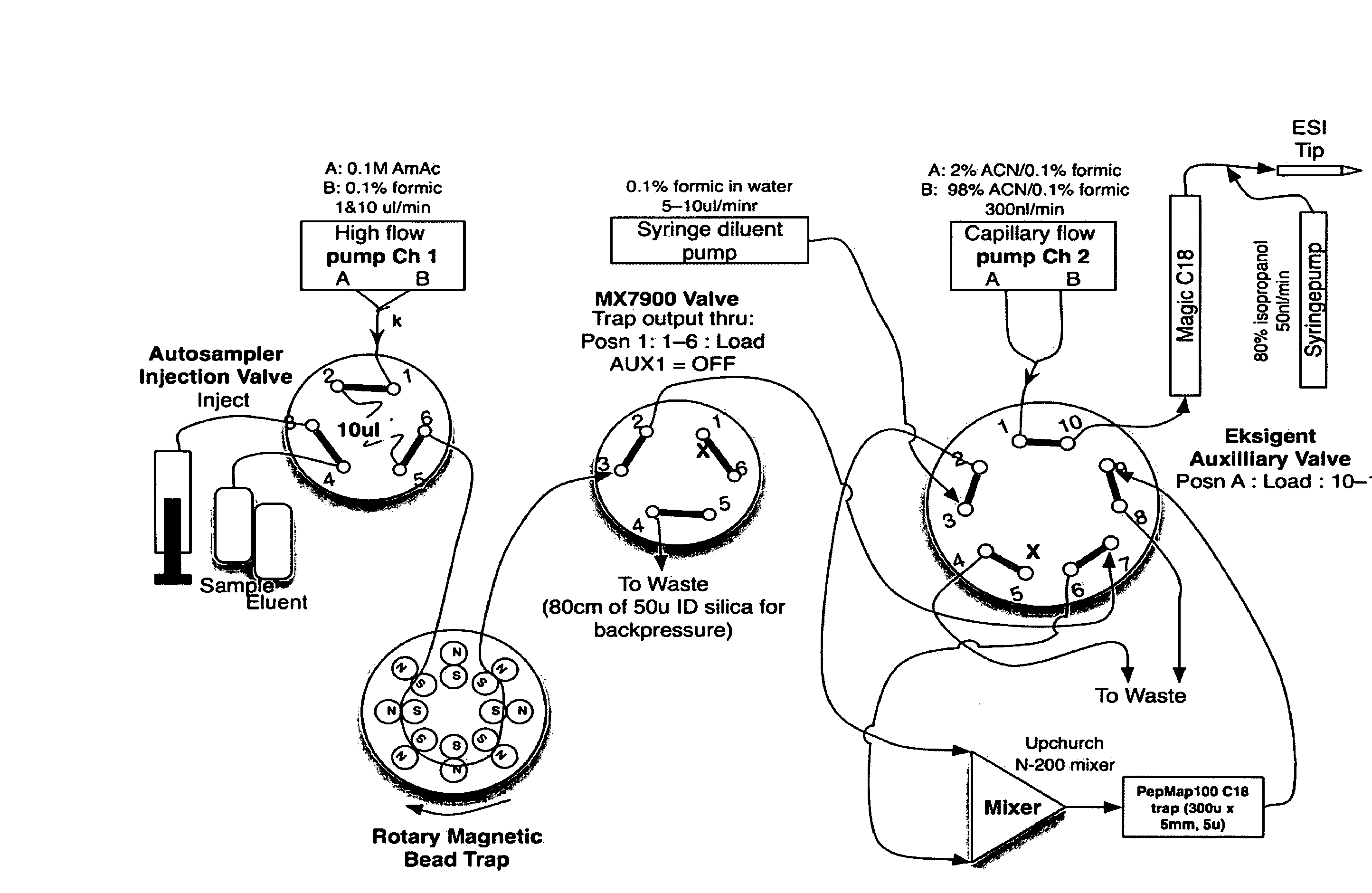
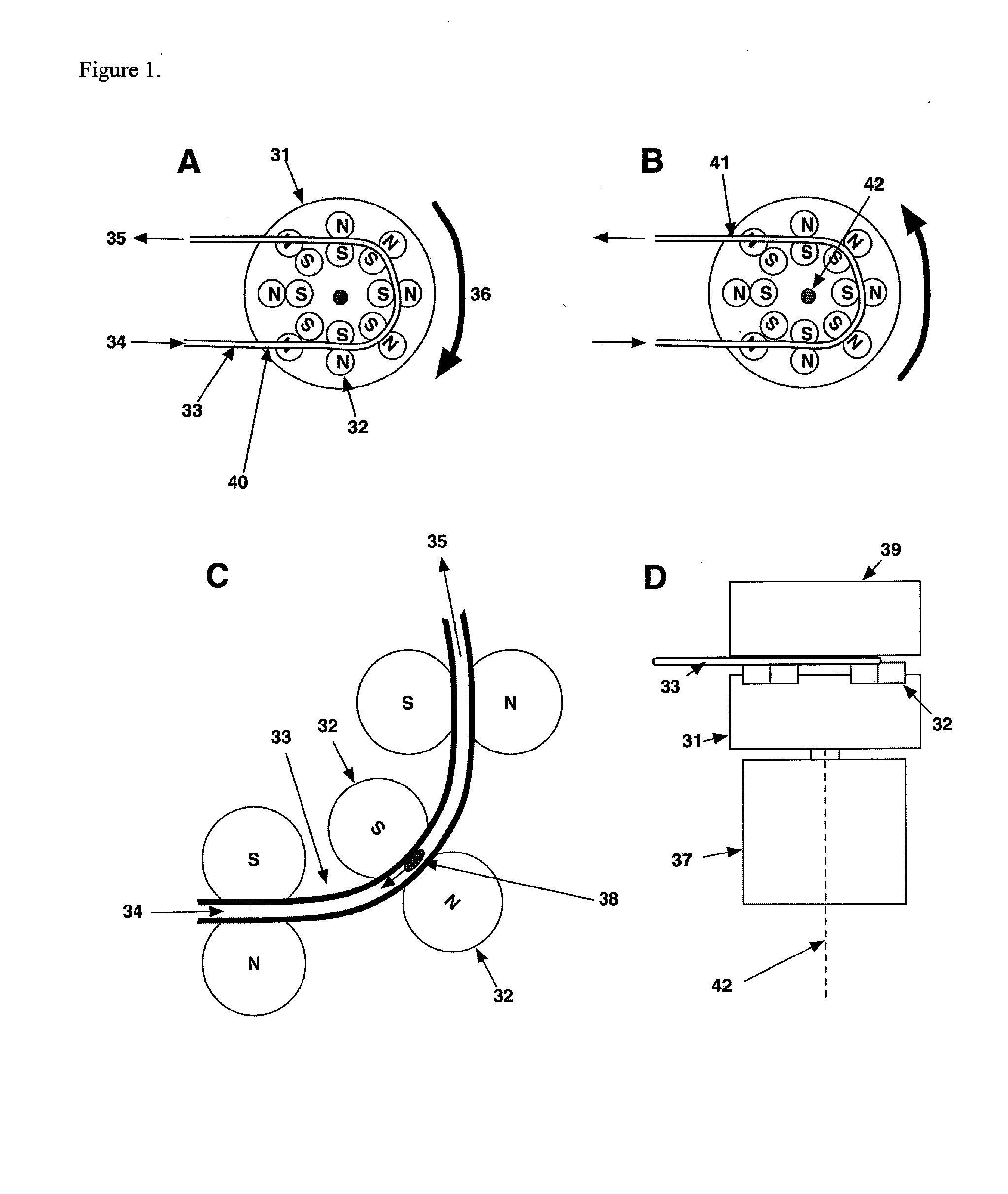
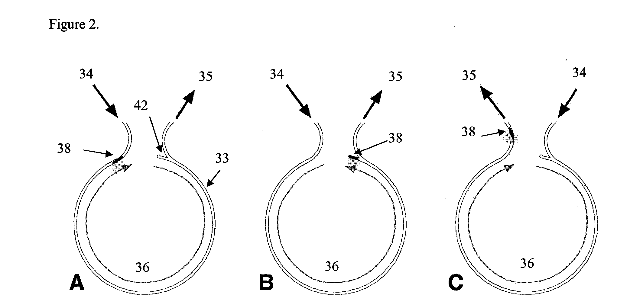
[0061]In a first example, a magnetic bead trap was constructed using ¼″ dia× 3 / 16″ thick cylindrical NdFeB magnets (Amazing Magnets, Inc.), pairs of which were held by epoxy glue on the end face of a cylindrical aluminum magnet carrier, which in turn was rotated about its cylinder axis by a reversible motor (a 2 RPM Oriental Motor SMK216A-GN / 2GN30KA Low-Speed Synchronous Motor). The magnet faces were arranged to be approximately co-planar on their upper surface. Direction of motor rotation was controlled by an AC relay, which was in turn was controlled by a solid-state relay controlled by either a contact closure signal from a Spark Holland autosampler auxiliary output under software control, or else by a manual toggle switch. A length of 150 u ID (360 u OD) Teflon capillary tubing (Upchurch Scientific) was configured to follow approximately 240 degrees of a circle of diameter the same as (and co-axial with) the circle of trapping regions (i.e., the circle defined by the contact poi...


PUM

PropertyMeasurementUnit
diameteraaaaaaaaaa
diameteraaaaaaaaaa
volumeaaaaaaaaaa

Abstract

A device and method for capture of magnetic beads in a rotary magnetic bead trap is disclosed. The device allows capture, washing, elution and ejection of beads in an automated system. Analyte is eluted in a small volume in a capillary-scale fluid system compatible with LC-MS/MS analysis.

Description

CROSS-REFERENCE TO RELATED APPLICATIONS[0001]This application claims priority to U.S. Provisional Patent Application 60 / 904,922 filed Mar. 5, 2007 and U.S. Provisional Patent Application 60 / 955,195 filed Aug. 10, 2007, both of which are incorporated herein by reference in their entirety.BACKGROUND[0002]Many techniques of molecular analysis involve specific capture or enrichment of one or more target molecules as a means of improving specificity or sensitivity of the analysis. When a target analyte is present at low concentration, and a successful method is available for enriching it to the level of detection, it is important that the enriched material be delivered for analysis with minimal subsequent contamination or dilution if the benefit of the enrichment is to be realized. When very small amounts of analytes are involved, this presents a major challenge, since small amounts of many substances can be bound by (and therefore lost upon) the surfaces of storage vessels, transporting...

Claims


Application Information

Patent Timeline
Patent Type & Authority Applications(United States)
IPC IPC(8): B03C1/00B01J19/08B01D59/44
CPCB01L3/0289B01L2200/0668G01N35/0098B01L2400/043B01L2300/0838
Inventor ANDERSON, N. LEIGH
Owner ANDERSON FORSCHUNG GROUP
Why Eureka
Try Eureka