Method and apparatus for producing single-wall carbon nanotubes

a carbon nanotube and single-wall technology, applied in the direction of carbonsing rags, energy-based chemical/physical/physical-chemical processes, chemical/physical/physical-chemical processes, etc., can solve the problems of limited use of cobalt vapor, single-wall carbon nanotube production via laser ablation and electric arc consumes a lot of energy for small quantities of nanotubes produced

Inactive Publication Date: 2008-09-18
INSTITUT NATIONAL DE LA RECHERCHE SCIENTIFIQUE
View PDF99 Cites 9 Cited by
  • Summary
  • Abstract
  • Description
  • Claims
  • Application Information

AI Technical Summary

Benefits of technology

[0007]It is therefore an object of the present invention to overcome the above drawbacks and to provide a method and apparatus for the continuous production of single-wall carbon nanotubes in large quantities.
[0026]Applicant has found quite surprisingly that by feeding the carbon-containing substance separately from the inert gas used to generate the primary plasma so that the carbon-containing substance contacts the primary plasma at the plasma-discharging end of the plasma tube to form the aforesaid secondary plasma, there is no undesirable formation of carbon deposit adjacent the plasma-discharging end of the plasma tube. Thus, no premature extinction of the plasma torch.
[0044]In the apparatus according to the third or fourth aspect of the invention, the condenser preferably comprise an oven disposed downstream of the plasma tube in spaced relation thereto, and a heat source for heating the oven to provide a temperature gradient permitting rapid condensation of the atoms or molecules of carbon and the atoms of metal catalyst. Preferably, a heat-resistant tubular member having a plasma-receiving end extends through the oven with the plasma-receiving end disposed upstream of the plasma-discharging end of the plasma tube. An injector is provided for injecting a cooling inert gas into the tubular member, downstream of the secondary plasma; the cooling inert gas assists in providing the temperature gradient. The heat-resistant tubular member can be made of quartz or boron nitride. The apparatus can be provided with a trap for collecting single-wall carbon nanotubes produced. Preferably, the trap is an electrostatic trap. The apparatus can also be provided with a cooling system disposed about the plasma tube and extends substantially coaxially thereof. Preferably, the apparatus comprises a Faraday shield made of a conductive material for preventing emission of electromagnetic radiations outside of the apparatus.

Problems solved by technology

However, single-wall carbon nanotubes are available only in small quantities since known methods of production do not produce more than few grams per day of these nanotubes.
The process involves contacting carbon vapor with cobalt vapor under specific conditions, and is thus limited to the use of cobalt vapor.
Although the above methods are relatively efficient for the transformation of carbon into nanotubes, they have inherent drawbacks.
Therefore, the production of single-wall carbon nanotubes via laser ablation and electric arc consumes a lot of energy for small quantities of nanotubes produced.
Moreover, these processes are non-continuous since they must be stopped for renewing the source of carbon once the graphite has been consumed.
The CVD method suffers from a major drawback since the encapsulation of the catalyst particles by carbon stops the growth of the nanotubes (R. E. Smalley et al.
In addition, due to the non-selectivity of the method, nanotubes having two, three or multi-walls are obtained at the same time as the single-wall nanotubes.
Such a method, however, has an important drawback since a premature extinction of the plasma torch occurs due to a rapid formation of carbon deposit in the torch.
This method is therefore non-continuous and requires removal of the carbon deposit.
Thus, large quantities of single-wall carbon nanotubes cannot be produced.

Method used


Image

  • Method and apparatus for producing single-wall carbon nanotubes
  • Method and apparatus for producing single-wall carbon nanotubes
  • Method and apparatus for producing single-wall carbon nanotubes

Examples


example

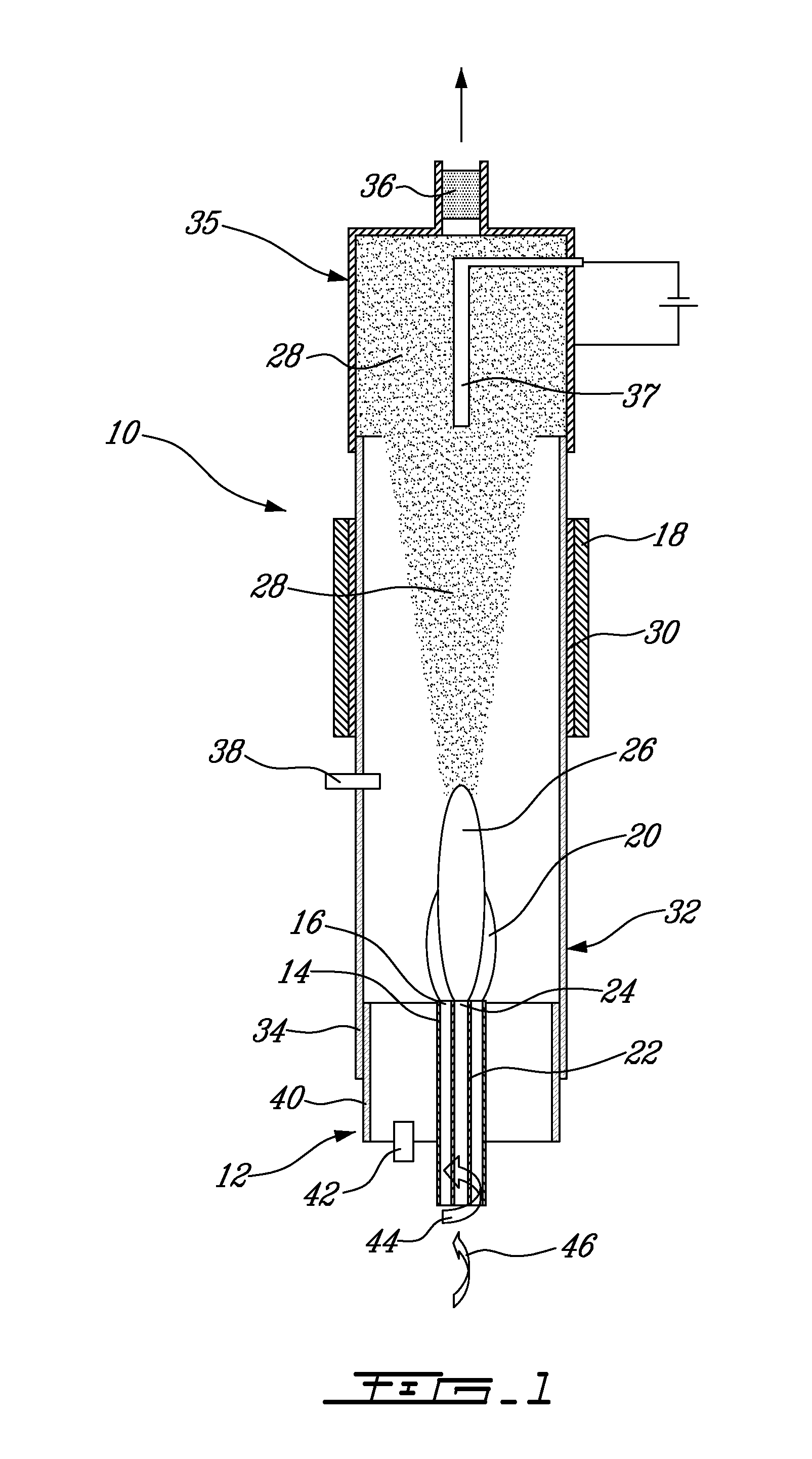
[0067]The production or synthesis of single-wall carbon nanotubes has been performed by using a plasma torch as illustrated in FIG. 1. The following experiment has been carried out by the inventors by providing the plasma torch with a cooling system and a Faraday shield. The cooling system prevents the plasma torch from over-heating and being damaged. The Faraday shield comprising a conductive material, preferably aluminium, prevents the electromagnetic radiations from escaping from said apparatus, thereby protecting users of the plasma torch. All the parameters related to the plasma torch are controlled by a computer using the LABVIEW® software. The parameters can also be manually controlled. The inert gas used for generating the primary plasma was argon, the metal catalyst was ferrocene, the carbon-containing gas was ethylene and the cooling gas was helium. Helium was also injected toward the plasma discharging end so as to prevent carbon deposit. The injecting device illustrated ...


PUM

PropertyMeasurementUnit
temperatureaaaaaaaaaa

Abstract

The invention relates to a method for producing single-wall carbon nanotubes. The method of the invention comprises the steps of (a) providing a plasma torch having a plasma tube with a plasma-discharging end; (b) feeding an inert gas through the plasma tube to form a primary plasma; (c) contacting a carbon-containing substance and a metal catalyst with the primary plasma at the plasma-discharging end of the plasma tube, to form a secondary plasma containing atoms or molecules of carbon and atoms of the metal catalyst; and (d) condensing the atoms or molecules of carbon and the atoms of the metal catalyst to form single-wall carbon nanotubes. Alternatively, steps (b) and (c) can be carried out by feeding an inert gas and an inorganic metal catalyst through the plasma tube to form a primary plasma containing atoms of the inorganic metal catalyst and contacting a carbon-containing substance with the primary plasma at the plasma-discharging end of the plasma tube, to form a secondary plasma containing atoms or molecules of carbon and the atoms of metal catalyst. An apparatus for carrying out the method according to the invention is also disclosed.

Description

FIELD OF THE INVENTION[0001]The present invention relates to improvements in the field of carbon nanotube production. More particularly, the invention relates to an improved method and apparatus for producing single-wall carbon nanotubes.BACKGROUND OF THE INVENTION[0002]Carbon nanotubes are available either as multi-wall or single-wall nanotubes. Multi-wall carbon nanotubes have exceptional properties such as excellent electrical and thermal conductivities. They have applications in numerous fields such as storage of hydrogen (C. Liu, Y. Y. Fan, M. Liu, H. T. Cong, H. M. Cheng, M. S. Dresselhaus, Science 286 (1999), 1127; M. S. Dresselhaus, K. A Williams, P. C. Eklund, MRS Bull. (1999), 45) or other gases, adsorption heat pumps, materials reinforcement or nanoelectronics (M. Menon, D. Srivastava, Phy. Rev. Lett. 79 (1997), 4453). Single-wall carbon nanotubes, on the other hand, possess properties that are significantly superior to those of multi-wall nanotubes. However, single-wall ...

Claims


Application Information

Patent Timeline
Patent Type & Authority Applications(United States)
IPC IPC(8): C01B31/00B01J19/00B01J19/08C01B31/02D01F9/127
CPCB01J19/088B01J2219/0871B01J2219/0875B01J2219/0892D01F9/127B82Y30/00B82Y40/00C01B31/0233C01B2202/02B01J2219/0894Y10S977/843Y10S977/844C01B32/162
Inventor SMILJANIC, OLIVIERSTANSFIELD, BARRY L.
Owner INSTITUT NATIONAL DE LA RECHERCHE SCIENTIFIQUE
Why Eureka
Try Eureka