Dielectric ceramics and multilayer ceramic capacitor

a technology of ceramic capacitors and dielectric ceramics, applied in the direction of ceramic layered products, stacked capacitors, fixed capacitor details, etc., can solve the problems of deterioration of the reliability of the inability to use low distortion capacitors in applications, etc., to achieve high accelerated life time

Inactive Publication Date: 2008-09-18
TAIYO YUDEN KK
View PDF5 Cites 9 Cited by
  • Summary
  • Abstract
  • Description
  • Claims
  • Application Information

AI Technical Summary

Benefits of technology

[0008]In one embodiment, the dielectric ceramics having a property showing reliability such as high accelerated life time which is improved more than usual, having temperature characteristic of the permittivity satisfying the X6S property, and having a permittivity of about 800 to about 1,800, as well as a multi-layer ceramic capacitor with internal Ni electrodes.

Problems solved by technology

The dielectric ceramic composition shown in JP No. 3567759 has a high accelerated life time and has sufficient reliability at the level of the thickness of a green sheet of 20 μm as described in the examples thereof, but it involves a problem that the property showing the reliability such as high accelerated life time is deteriorated at the level of a thickness for one layer of the ceramic layers of 10 μm or less after burning.
Further, while a low distortion capacitor with less distortion has been demanded in recent years, the dielectric ceramic composition shown in JP No. 3361531 has a permittivity as high as 7,000 or more and is suitable to increase of the capacity but it is not suitable to the application use for low distortion capacitors.

Method used


Image

  • Dielectric ceramics and multilayer ceramic capacitor
  • Dielectric ceramics and multilayer ceramic capacitor

Examples


example 1

[0025]As the starting material, BaCO3, TiO2, ZrO2, Gd2O3, and MgO were provided so as to obtain sintered bodies of the compositions shown in Table 1.

[0026]In Table 1, Ba, Ti, and Zr are represented by the ratios based on Ti+Zr being assumed as 100.

TABLE 1SpecimenRe:aM:bAidNo.BaTiZrBa / TiKindAmountKind 1AmountKind 2AmountSiO2 101*102.094.06.01.085Gd0.08Mg0.025Mn0.0051.5102100.191.09.01.100Gd0.08Mg0.025Mn0.0051.5103102.060.040.01.700Gd0.04Mg0.025Mn0.0053.0 104*105.060.040.01.750Gd0.04Mg0.025Mn0.0053.0 105*107.097.03.01.103Gd0.06Mg0.025Mn0.0051.5106105.095.05.01.105Gd0.04Mg0.025Mn0.0051.5107101.560.040.01.693Gd0.04Mg0.025Mn0.0053.0 108*93.055.045.01.691Gd0.04Mg0.025Mn0.0053.0*Out of the range of the invention

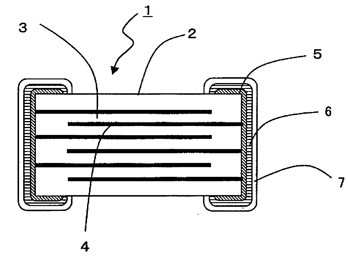
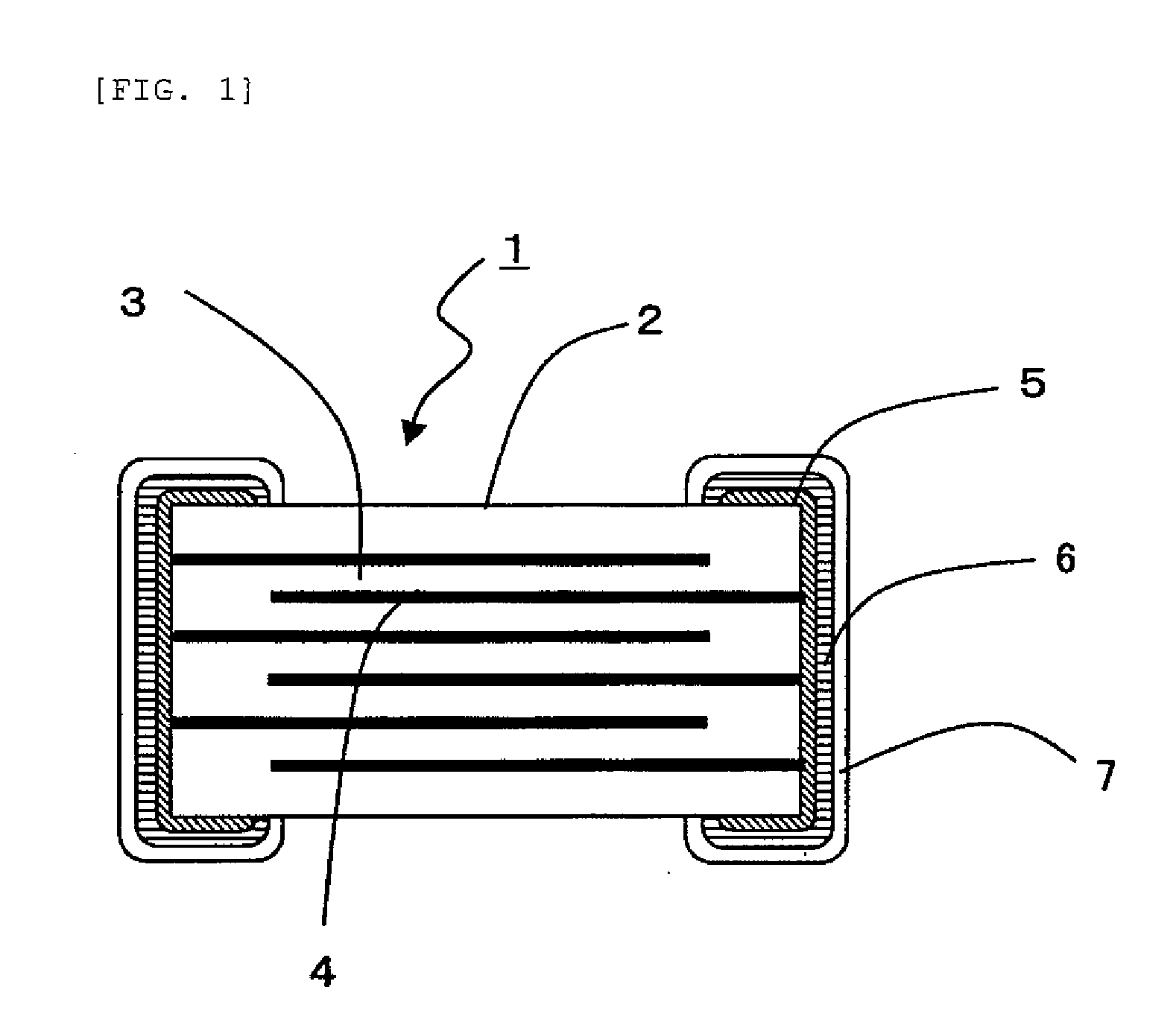
[0027]The BaCO3, TiO2, and ZrO2 were wet-mixed by a ball mill and, after drying, calcined at 1,100° C. to obtain a perovskite structure. Then, Gd2O3, MgO, MnO, and SiO2 were added to the perovskite structure so as to provide compositions shown in Table 1, wet-mixed by a ball mill an...

example 2

[0030]Dielectric ceramic powders were formed in the same manner as in Example 1 so as to obtain sintered bodies of the compositions shown in Table 3. In this example, the addition amount of the Re ingredient was increased or decreased to verify the effect thereof.

TABLE 3SpecimenRe:aM:bAidNo.BaTiZrBa / TiKind 1AmountKind 2AmountKind 1AmountKind 2AmountSiO2201101.585.015.01.194La0.03Gd0.03Mg0.025Mn0.0051.5202101.585.015.01.194Ce0.03Gd0.03Mg0.025Mn0.0051.5203101.585.015.01.194Pr0.03Gd0.03Mg0.025Mn0.0051.5204101.585.015.01.194Nd0.03Gd0.03Mg0.025Mn0.0051.5205101.585.015.01.194Sm0.03Ho0.03Mg0.025Mn0.0051.5206101.585.015.01.194Eu0.03Ho0.03Mg0.025Mn0.0051.5207101.285.015.01.191Tb0.06——Mg0.025Mn0.0051.5208101.285.015.01.191Dy0.06——Mg0.025Mn0.0051.5209101.285.015.01.191Ho0.06——Mg0.025Mn0.0051.5210101.285.015.01.191Er0.04Gd0.02Mg0.025Mn0.0051.5211101.285.015.01.191Tm0.04Gd0.02Mg0.025Mn0.0051.5212101.285.015.01.191Yb0.04Gd0.02Mg0.025Mn0.0051.5213101.285.015.01.191Lu0.04Gd0.20Mg0.025Mn0.0051.52141...

example 3

[0033]Dielectric ceramic powders were formed in the same manner as in Example 1 so as to obtain sintered bodies of the compositions shown in Table 5. In this example, the addition amount of the M ingredient was increased or decreased to verify the effect thereof.

TABLE 5SpecimenRe:aM:bAidNo.BaTiZrBa / TiKindAmountKind 1AmountKind 2AmountSiO2301101.582.018.01.238Gd0.06Al0.030Mn0.0051.5302101.582.018.01.238Gd0.06Cr0.030Mn0.0051.5303101.582.018.01.238Gd0.06Fe0.030Mn0.0051.5304101.582.018.01.238Gd0.06Ni0.030Mn0.0051.5305101.582.018.01.238Gd0.06Cu0.030Mn0.0051.5306101.582.018.01.238Gd0.06Zn0.030Mn0.0051.5307101.582.018.01.238Gd0.06V0.020Mn0.0051.5 308*101.582.018.01.238Gd0.06Mg0.0025Mn0.00251.5309101.582.018.01.238Gd0.06Mg0.005Mn0.0051.5310101.582.018.01.238Gd0.06Mg0.045Mn0.0051.5 311*101.582.018.01.238Gd0.06Mg0.055Mn0.0051.5*Out of the range of the invention

[0034]In the same manner as in Example 1, the dielectric ceramic powders described above were formed into multi-layer ceramic capacito...


PUM

PropertyMeasurementUnit
thicknessaaaaaaaaaa
thicknessaaaaaaaaaa
thicknessaaaaaaaaaa

Abstract

Dielectric ceramics and a multi-layer ceramic capacitor with internal Ni electrodes having a more improved property showing the reliability such as high accelerated life time than usual, a temperature characteristic of the permittivity satisfying the X6S property, and having a permittivity of from 800 to 1800, wherein the dielectric ceramics comprise a main ingredient within a range:
1.100≦Ba/Ti≦1.700
0.02≦a≦0.10
0.01≦b≦0.05
when represented as:
ABO3+aRe+bM
(in which ABO3 is a general formula for a perovskite structure, wherein the A cation sites are predominantly occupied by Ba and optionally one or more of Ca and Sr, and wherein the B cation sites are predominantly occupied by Ti and Zr, wherein Re represents at least one oxide of metals selected from La, Ce, Pr, Nd, Sm, Eu, Gd, Tb, Dy, Ho, Er, Tm, Yb, Lu, and Y, wherein M is an oxide of metal element selected from Mg, Al, Cr, Mn, Fe, Ni, Cu, and Zn, wherein a and b each represents the number of mols for each oxide based on 1 mol of ABO3 when each oxide is converted into that of a chemical formula containing one metal element), and wherein the Zr is within a range, when represented as a ratio of Zr to Ti, of; Ti:Zr=95:5 to 60:40.

Description

BACKGROUND OF THE INVENTION[0001]1. Field of the Invention[0002]The present invention concerns dielectric ceramics mainly comprising barium titanate (BaTiO3) and a multi-layer ceramic capacitor and using them to provide a multi-layer ceramic capacitor having internal electrodes constituted with Ni or an Ni alloy.[0003]2. Description of Related Art[0004]For multi-layer ceramic capacitors used in electronic equipments such as portable equipments and communication equipments, decrease in the size and increase in the capacity have been demanded more and more. For manufacturing a multi-layer ceramic capacitor small in the size and large in the capacity, Japanese Patent No. 3567759 discloses, for example, a dielectric ceramic composition comprising a perovskite structure and additive ingredients decreased in the loss and heat generation under high frequency and high voltage.[0005]Further, Japanese Patent No. 3361531 proposes a dielectric ceramic composition mainly comprising barium titana...

Claims


Application Information

Patent Timeline
Patent Type & Authority Applications(United States)
IPC IPC(8): B32B18/00C03C3/00
CPCB32B18/00C04B2237/704C04B2237/68C04B2237/346H01G4/12H01G4/30
Inventor KANEDA, KAZUMIUEDA, SHUSAKUIKEMI, SHINICHIRO
Owner TAIYO YUDEN KK
Why Eureka
Try Eureka