Lead Storage Battery

Inactive Publication Date: 2008-10-02
PANASONIC CORP
View PDF4 Cites 17 Cited by
  • Summary
  • Abstract
  • Description
  • Claims
  • Application Information

AI Technical Summary

Benefits of technology

[0034]According to the present invention, a lead storage battery with a longer service life and high reliability can be obtained under a usage mode in which charge/discharge is frequently repeated under a comparatively low SOC range, since chargeability is improved and

Problems solved by technology

Thus, in comparison with conventional lead storage batteries for starting engines, SOC of the lead storage battery inevitably becomes low.
Further, an increase in dark current accompanied with vehicle parts increasingly becoming electrically powered, a discharge of the lead storage battery advances while the vehicle is stopped for a long period of time, thereby leaving a possibility for an over discharge.
Thus, a sufficient amount of charged electricity of the lead storage battery cannot be secured, thereby rendering the battery to be in an undercharged state.
However, when a lead storage battery is to be used in a vehicle equipped with the above stop-and-go-system or the regenerative-braking-system, that is, when a lead storage battery is to be used in a mode in which charge/discharge is repeated under a lower SOC range, there was a problem in that corrosion easily advances in the tab of negative electrode grid, although the chargeability can be secured.
When the corrosion advances in the negative-electrode-grid-tab, current collecting efficiency of the negative electrode plate declines due to a decrease in a thickness of the tab, thereby shortening its service life.
The decrease in a thickness of the negative-electrode-grid-tab also weakens strength of the tab, in addition to the decline in the current collecting efficiency.
Especially, in batteries mounted on vehicles, since vibrations and impacts are constantly applied to the vehicle wh

Method used


Image

  • Lead Storage Battery
  • Lead Storage Battery
  • Lead Storage Battery

Examples


Example

EXAMPLE 1

(1) Fabrication of Bag-shaped Separator

[0097]To polyethylene with an average molecular weight of 8000000, silica particles, a mineral oil (Daphne Oil CP, manufactured by Idemitsu Kosan Co., Ltd.), and carbon powder were added and then kneaded. After molding the kneaded matter by extrusion, the mineral oil was removed by a solvent such as hexane, to obtain a polyethylene sheet including silica particles, having fine pores of a pore diameter of not more than 1 μm, and having a thickness of 0.3 mm. The polyethylene sheet thus obtained was folded to two, and a bag-shaped separator with an opening only on an upper part was obtained by welding a left end side and a right end side of the folded sheet with heat.

[0098]For the silica particles, porous particles (a particle diameter: 5 to 40 μm) having fine pores with an average pore diameter of not more than 20 μm were used.

(2) Fabrication of Positive Electrode Plate

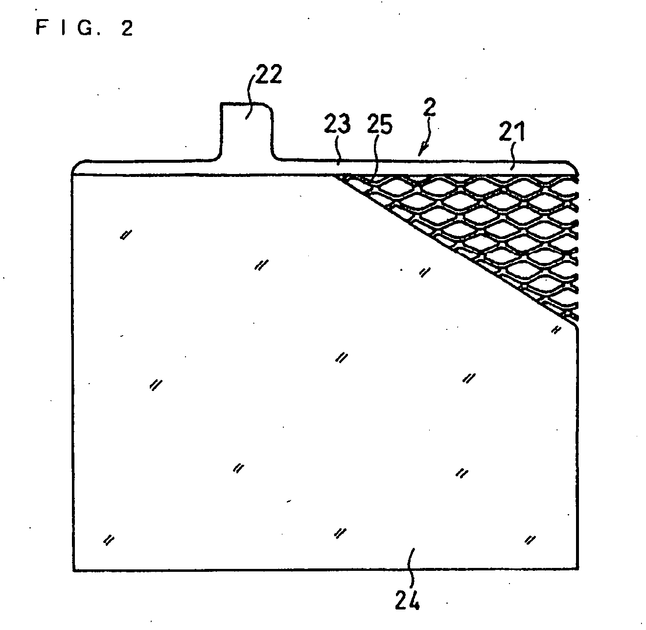
[0099]A positive electrode plate 2 shown in FIG. 2 was made as in th...

Example

EXAMPLE 2

[0134]A glass fiber mat with a thickness of 1.0 mm retaining silica particles was obtained by papermaking process of a glass fiber in an acidic aqueous solution in which silica particles were dispersed. Then, the obtained glass fiber mat was folded to two, and a bag-shaped separator with an opening only on top was made by welding a left end part and a right end part by heating. At this time, the silica particle content in the separator comprising the glass fiber mat retaining the silica particles was set to become 0% by mass, 5% by mass, 10% by mass, 40% by mass, and 50% by mass. For the silica particles, the same silica particles as in Example 1 were used.

[0135]As shown in Tables 3 and 4, batteries K1 to K5, L1 to L5, M1 to M5, N1 to N5, O1 to O5, P1 to P5, Q1 to Q5, R1 to R5, S1 to S5, and T1 to T5 were made in the same manner as in Example 1, by combining the separators comprising the glass fiber mat retaining the silica particles with different silica particle contents,...

Example

EXAMPLE 3

[0146]As shown in FIG. 5, a lead alloy foil 27a was supplied with a base material sheet 27 in between a pair of rollers 45, and the base material sheet 27 and the lead alloy foil 27a were simultaneously pressed by the rollers, in a pressing step of a positive electrode grid fabrication. By this pressing process, the lead alloy foil 27a was attached onto the base material sheet 27, and a composite sheet having a lead alloy layer with a thickness of 20 μm on one side of the base material sheet with a thickness of 1.1 mm was obtained. A Pb alloy containing 5.0% by mass of Sn was used for the lead alloy foil 27a. The same positive electrode grid as in Example 1 was used for the base material sheet 27.

[0147]For the part of the base material sheet 27 where the lead alloy foil 27a is to be pressed onto, only a part where an expanded mesh and a frame are to be formed in an expanding process mentioned later was pressed, and the lead alloy foil was not pressed onto a center part of t...


PUM


Abstract

A lead storage battery of the present invention has an electrode plate pack comprising a plurality of negative electrode plates in each of which a negative electrode active material layer is retained by a negative electrode grid, a plurality of positive electrode plates in each of which a positive electrode active material layer is retained by a positive electrode grid, and a plurality of separators separating the positive electrode plate and the negative electrode plate; a positive electrode connecting member connected to each positive electrode plate of the electrode plate pack, and a negative electrode connecting member connected to each negative electrode plate of the electrode plate pack. The positive and negative electrode grids, and the positive and negative electrode connecting members comprise a Pb alloy including at least one of Ca and Sn; the negative electrode active material layer includes Sb; and the separator includes silica.

Description

TECHNICAL FIELD[0001]The present invention relates to lead storage batteries. More particularly, the present invention relates to an improvement in service life properties of lead storage batteries used for vehicles carrying a stop-and-go-system and a regenerative-braking-system.BACKGROUND ART[0002]Conventionally, lead storage batteries have been used for starting an engine and for a back-up power source of a vehicle. Among these usages, lead storage batteries for starting an engine function to supply electricity to various electric and electronic devices mounted on vehicles, in addition to a cell motor for starting the engine. After starting the engine, the lead storage battery is charged by an alternator. An output voltage and an output current of the alternator are set so that SOC (state of charge) of the lead storage battery is maintained to be 90 to 100%.[0003]In recent years, a demand for an improvement in fuel-efficiency of the vehicle is increasing, in view of environmental ...

Claims


Application Information

Patent Timeline
IPC IPC(8): H01M2/28H01M4/38H01M4/02H01M4/14H01M4/62H01M10/06H01M50/417H01M50/431H01M50/437H01M50/466H01M50/491H01M50/536H01M50/541
CPCH01M2/1613Y02E60/126H01M2/1646H01M2/1653H01M2/166H01M2/18H01M2/266H01M2/28H01M4/14H01M4/38H01M4/57H01M4/627H01M4/73H01M10/06H01M2004/027H01M2/162Y02E60/10H01M50/431H01M50/44H01M50/446H01M50/437H01M50/417H01M50/466H01M50/491H01M50/536H01M4/62H01M4/662H01M4/72H01M4/387H01M50/434H01M4/745H01M50/463
Inventor SUGIE, KAZUHIROSHIMODA, KAZUHIKOMUROCHI, SHOZOYOSHIMURA, TSUNENORIIWASAKI, SHINICHIHORIE, SHOJIYONEMURA, KOICHI
Owner PANASONIC CORP
Why Eureka
Try Eureka