Resin-coated ferrite carrier for electrophotographic developer and electrophotographic developer using the resin-coated ferrite carrier

a technology of resin-coated ferrite and electrophotographic developer, which is applied in the direction of pigmenting treatment, iron compounds, instruments, etc., can solve the problems of frictional chargeability with toner particles, deterioration of frictional chargeability, and high magnetization rate, and achieves small standard deviation, good sphericity and average particle size, and hardly any variation

Active Publication Date: 2008-10-02
POWDERTECH
View PDF17 Cites 7 Cited by
  • Summary
  • Abstract
  • Description
  • Claims
  • Application Information

AI Technical Summary

Benefits of technology

[0028]The resin-coated ferrite carrier for an electrophotographic developer according to the present invention has good sphericity and average particle size, small standard deviations thereof and hardly any variation. Thus, when used with a toner as a developer, the startup properties are very good.

Problems solved by technology

However, the true specific gravity of such an iron powder carrier is about 7.8, which is heavy, and its magnetization is too high.
Due to the occurrence of toner spent, the effective carrier surface area decreases, whereby the frictional chargeability with the toner particles tends to deteriorate.
With a resin-coated iron powder carrier, the resin on the surface may peel away due to stress during use, causing charge to leak as a result of the high conductance, low breakdown voltage core material (iron powder) being exposed.
The electrostatic latent image formed on the photoreceptor breaks down as a result of such charge leakage, thus causing brush strokes or the like to occur on the solid portions, which makes it difficult to obtain a uniform image.
However, Japanese Patent Laid-Open No. 2006-38961 only defines sphericity and surface roughness, and does not define the variation in sphericity.
Further, there is no definition of the BET specific surface area or apparent density of the core material.
However, Japanese Patent Laid-Open No. 10-39549 only defines the specific resistance of the carrier core particles, and contains no description concerning the BET specific surface area or apparent density.
As described in Japanese Patent Laid-Open No. 10-39549, simply defining specific resistance would not be expected to improve startup properties when used in a developer.
Thus, an improvement in startup properties when used in a developer cannot be expected with a resin-coated carrier such as that described in Japanese Patent Laid-Open No. 2000-172019.

Method used


Image

  • Resin-coated ferrite carrier for electrophotographic developer and electrophotographic developer using the resin-coated ferrite carrier
  • Resin-coated ferrite carrier for electrophotographic developer and electrophotographic developer using the resin-coated ferrite carrier
  • Resin-coated ferrite carrier for electrophotographic developer and electrophotographic developer using the resin-coated ferrite carrier

Examples


example 1

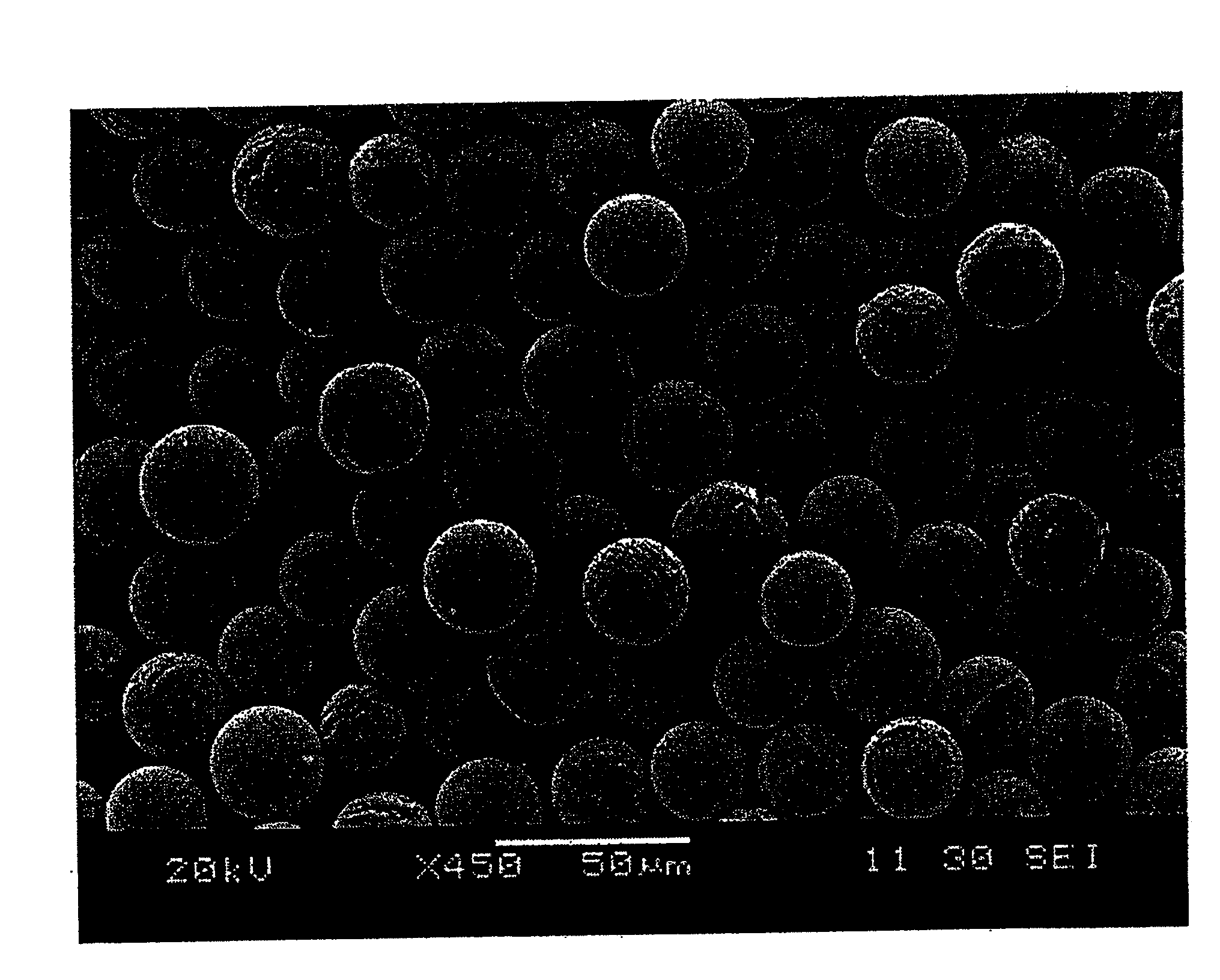
[0083]Iron oxide (Fe2O3), manganese oxide (MnO) and magnesium oxide (MgO) were weighed out in a mole ratio of 50:40:10. Further, to total of 100 moles of these compounds, 0.8 moles of strontium oxide (SrO) were added, and the resultant mixture was mixed together. The mixture was charged with water and then pulverized to produce a slurry having a solid content of 50% by weight. The produced slurry was granulated using a spray dryer, and the granules were classified to obtain granulated matter having an average particle size of 30 μm.

[0084]Next, the obtained granulated matter was thermally sprayed into water by injecting at a flow rate of about 40 m / sec into a combustible gas combustion flame having a propane:oxygen ratio of 8 Nm3 / hr:32 Nm3 / hr. The resultant matter rapidly cooled, and was then recovered from the water, dried and classified to produce ferrite particles (ferrite carrier core material).

[0085]The BET specific surface area, apparent density, long axis / short axis ratio (ave...

example 2

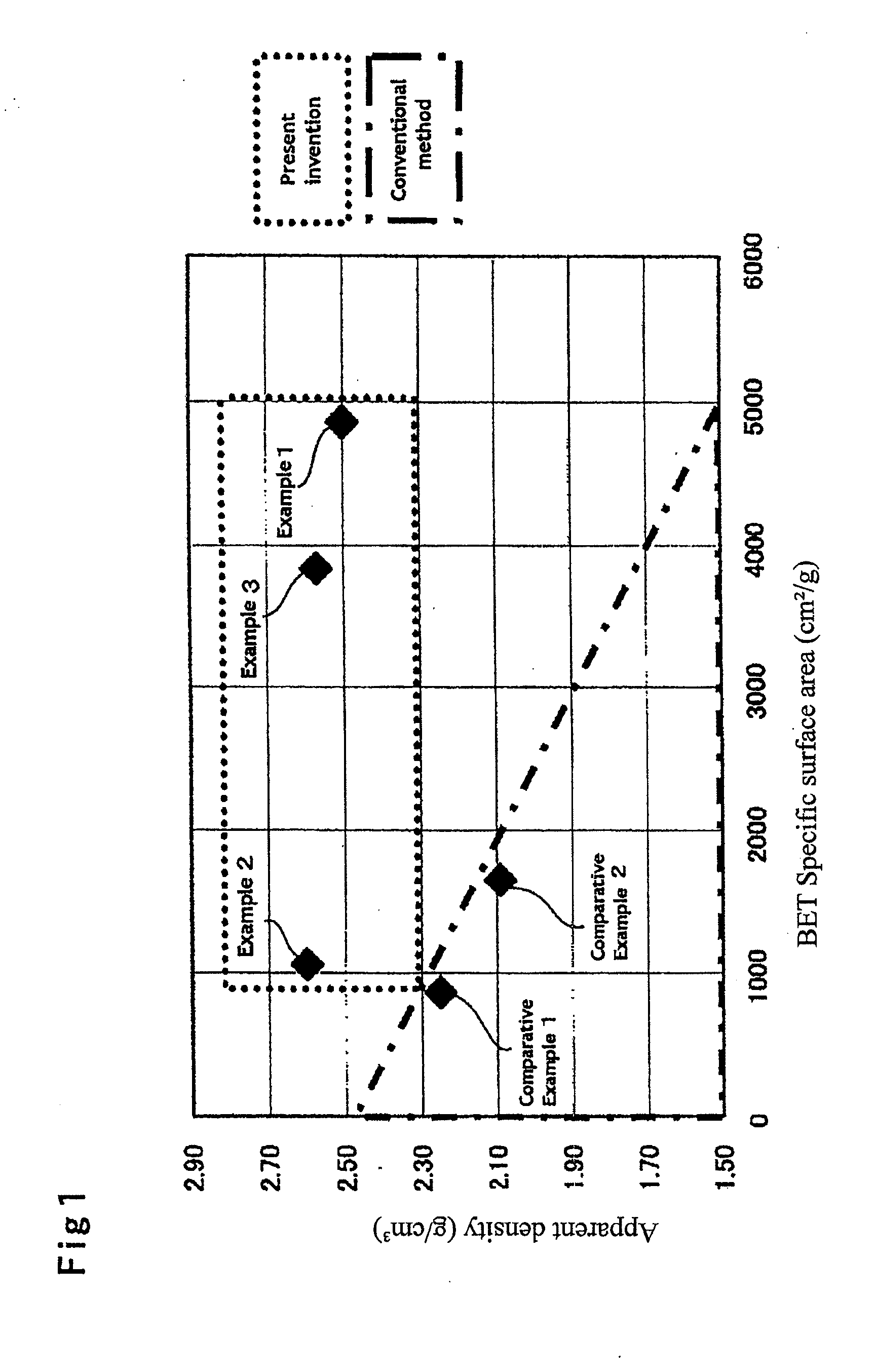
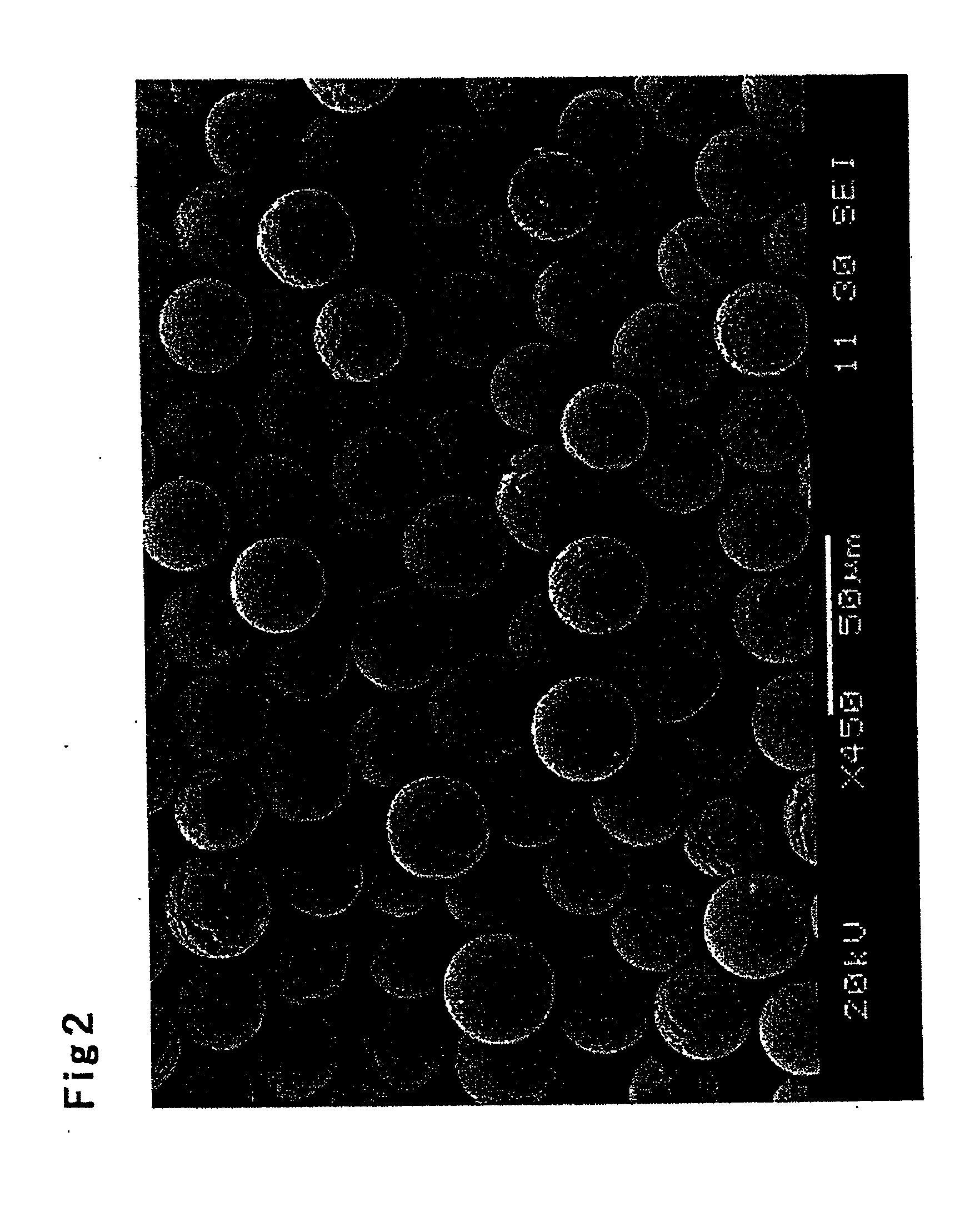
[0094]Granulated matter was obtained and then ferrite particles (ferrite carrier core material) produced in the same manner as in Example 1, except that iron oxide (Fe2O3) was used as the ferrite raw material. The BET specific surface area, apparent density, long axis / short axis ratio (average value, standard deviation and percentage 1.10 or more), circle equivalent diameter (number average diameter, standard deviation and percentage 19.3 μm or less), magnetization and resistivity of the obtained ferrite carrier core material were measured in the same manner as in Example 1. The results are shown in Table 1. Further, the plotted relationship between BET specific surface area and apparent density is shown in FIG. 1.

[0095]The ferrite carrier core material was coated with a resin using the same silicone resin as in Example 1, then baked and subjected to magnetic selection to produce a resin-coated ferrite carrier. Charge amount was measured by the same method as in Example 1. The measu...

example 3

[0096]Granulated matter was obtained and then ferrite particles (ferrite carrier core material) produced in the same manner as in Example 1, except that iron oxide (Fe2O3) and manganese oxide (MnO) were used as the ferrite raw material in a mole ratio of 80:20. The BET specific surface area, apparent density, long axis / short axis ratio (average value, standard deviation and percentage 1.10 or more), circle equivalent diameter (number average diameter, standard deviation and percentage 19.3 μm or less), magnetization and resistivity of the obtained ferrite carrier core material were measured in the same manner as in Example 1. The results are shown in Table 1. Further, the plotted relationship between BET specific surface area and apparent density is shown in FIG. 1.

[0097]The ferrite carrier core material was coated with resin in the same manner as in Example 1, except that the silicone resin was changed to an acrylic resin (BR-52, manufactured by Mitsubishi Rayon Co., Ltd.), then ba...


PUM


Abstract

Employed are a resin-coated ferrite carrier for an electrophotographic developer including a ferrite carrier core material having a BET specific surface area of 900 to 5,000 cm2 / g and an apparent density of 2.30 to 2.80 g / cm3, and the electrophotographic developer using this resin-coated ferrite carrier.

Description

TECHNICAL FIELD[0001]The present invention relates to a resin-coated ferrite carrier for an electrophotographic developer used in a two-component electrophotographic developer used in copiers, printers and the like and an electrophotographic developer using this resin-coated ferrite carrier. More specifically, the present invention relates to a resin-coated ferrite carrier for an electrophotographic developer having good startup properties and high sphericity when used with a toner as a developer, and an electrophotographic developer using this resin-coated ferrite carrier.BACKGROUND ART[0002]Electrophotographic developing methods develop by adhering toner particles in a developer to an electrostatic latent image which is formed on a photoreceptor. The developer used in such methods can be classified as either being a two-component developer composed of toner particles and carrier particles, or a one-component developer which only uses toner particles.[0003]Among such developers, as...

Claims


Application Information

Patent Timeline
Patent Type & Authority Applications(United States)
IPC IPC(8): G03G9/083
CPCG03G9/10G03G9/113G03G9/1075G03G9/107C01G49/0072C01P2004/54C01P2004/03C01P2006/12C01P2004/32C01P2004/61C01P2006/42C09C1/22C01G49/0018G03G9/1085
Inventor KAYAMOTO, KANAOSHINMURA, ISSEI
Owner POWDERTECH
Why Eureka
Try Eureka