Method for Producing Biomaterial Scaffolds

a biomaterial and scaffold technology, applied in the field of multi-layered scaffolds, can solve the problems of limited regenerative capacity of damaged cartilage, non-biological relevance of 2d systems, and a typical ill-defined porous structure of 3d scaffolds

Inactive Publication Date: 2008-11-13
TRUSTEES OF TUFTS COLLEGE
View PDF2 Cites 74 Cited by
  • Summary
  • Abstract
  • Description
  • Claims
  • Application Information

AI Technical Summary

Problems solved by technology

However, the 3D scaffolds are typically ill-defined porous structures.
Well defined 2D patterning is often explored through microcontact printing, self-assembled monolayers and similar experimental strategies, however, 2D systems are being recognized as non-biologically relevant due to the universal presence of cells in a 3D environment in vivo.
Unfortunately, damaged cartilage has limited regenerative capacity; thus, over 1 million patients per year in the United States require some form of treatment.
Currently these treatments result in limited pain relief and / or restorative tissue function [5-10].
While many useful insights into cartilage related outcomes have been gained from these studies, there remains a significant gap in cell-matrix understanding and there is a need to move toward more functional and relevant cartilage outcomes.
However, the technique does not appear to allow for great control of geometry within the scaffold since it is based on a network of cylindrical fibers.

Method used


Image

  • Method for Producing Biomaterial Scaffolds
  • Method for Producing Biomaterial Scaffolds
  • Method for Producing Biomaterial Scaffolds

Examples


example 1

Layered Scaffolds

[0072]1.3.1. Bio-LOM Process (LOM stands for laminated object manufacturing; Bio-LOM refers to the technique which includes lining the scaffold with organic materials, such as bacterial cellulose)

[0073]The techniques for soft lithography [37] are applied to thermal lamination.

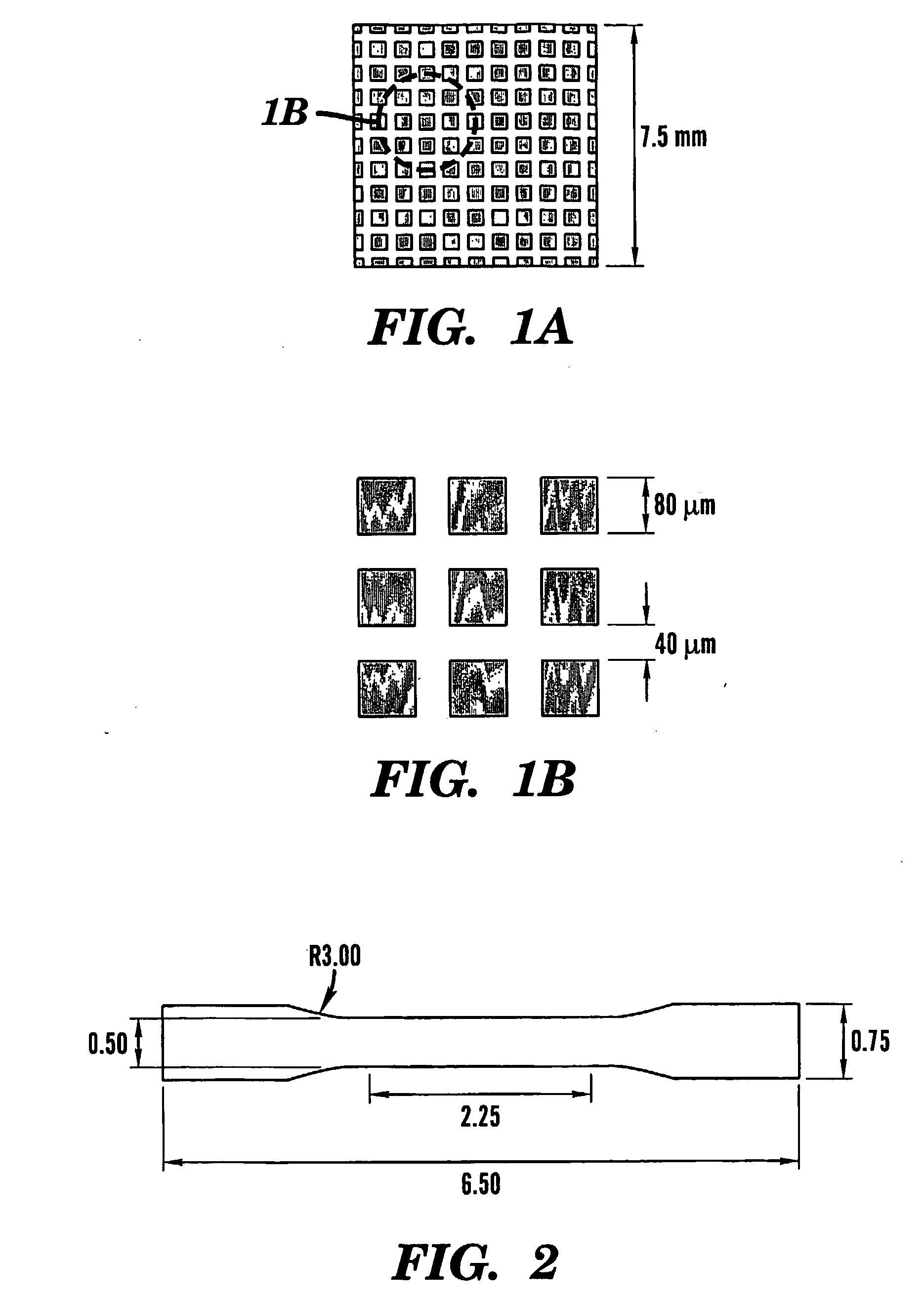
[0074]1.3.1.1. Advanced etching was used to make a silicon master of a die with user-defined pattern. As seen in FIG. 1, a grid pattern (80 μm square sections with spacing of 40 μm) was designed using Intellisuite 0 software (Intellisuite Software, Woburn, Mass.). A photolithographic mask of the desired pattern was made by depositing a thin film of chromium onto a flat glass panel (Benchmark Technologies, Lynnfield, Mass.) The mask was sent to a silicon foundry service (MEMS Exchange, Reston, Va.) for Deep Reactive Ion Etching (DRIE) onto a silicon wafer to a vertical depth of 90 μm. Prior to etching, the mask was used to photochemically cure a thin layer of photoresist on the areas of the wafe...

example 2

Simplified Method for Scaffold Fabrication

[0085]2.1.1. Improved Bio-LOM process

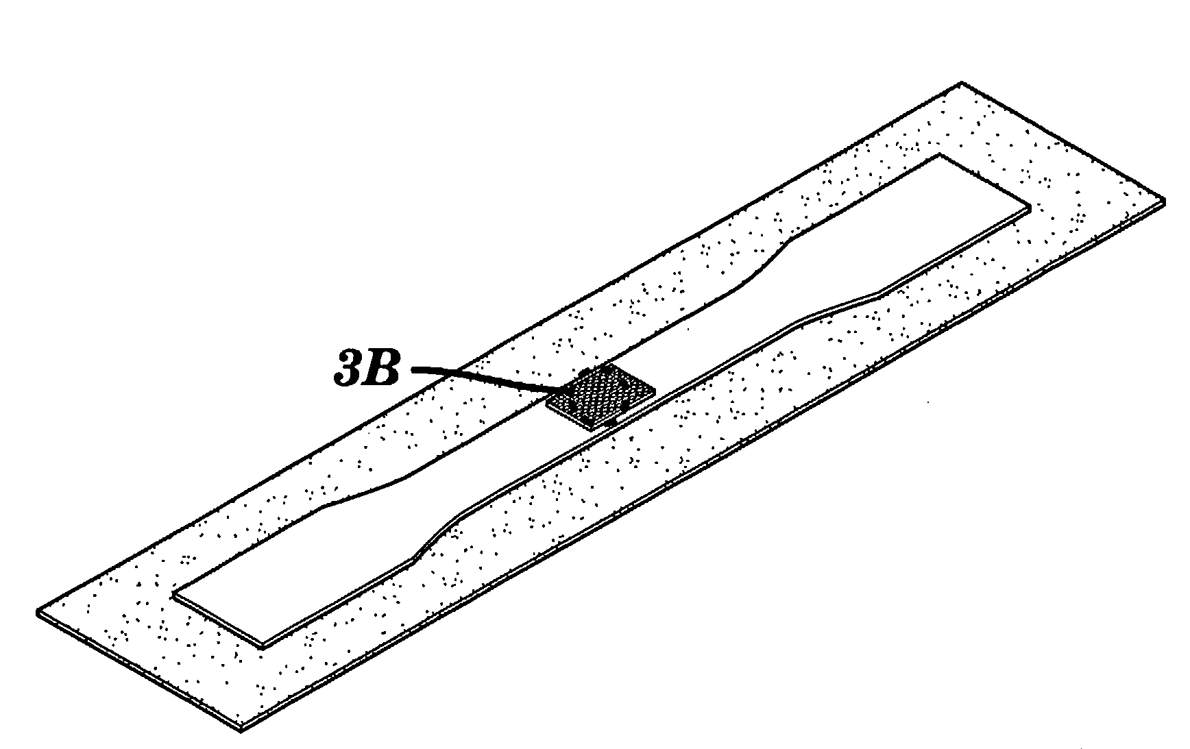
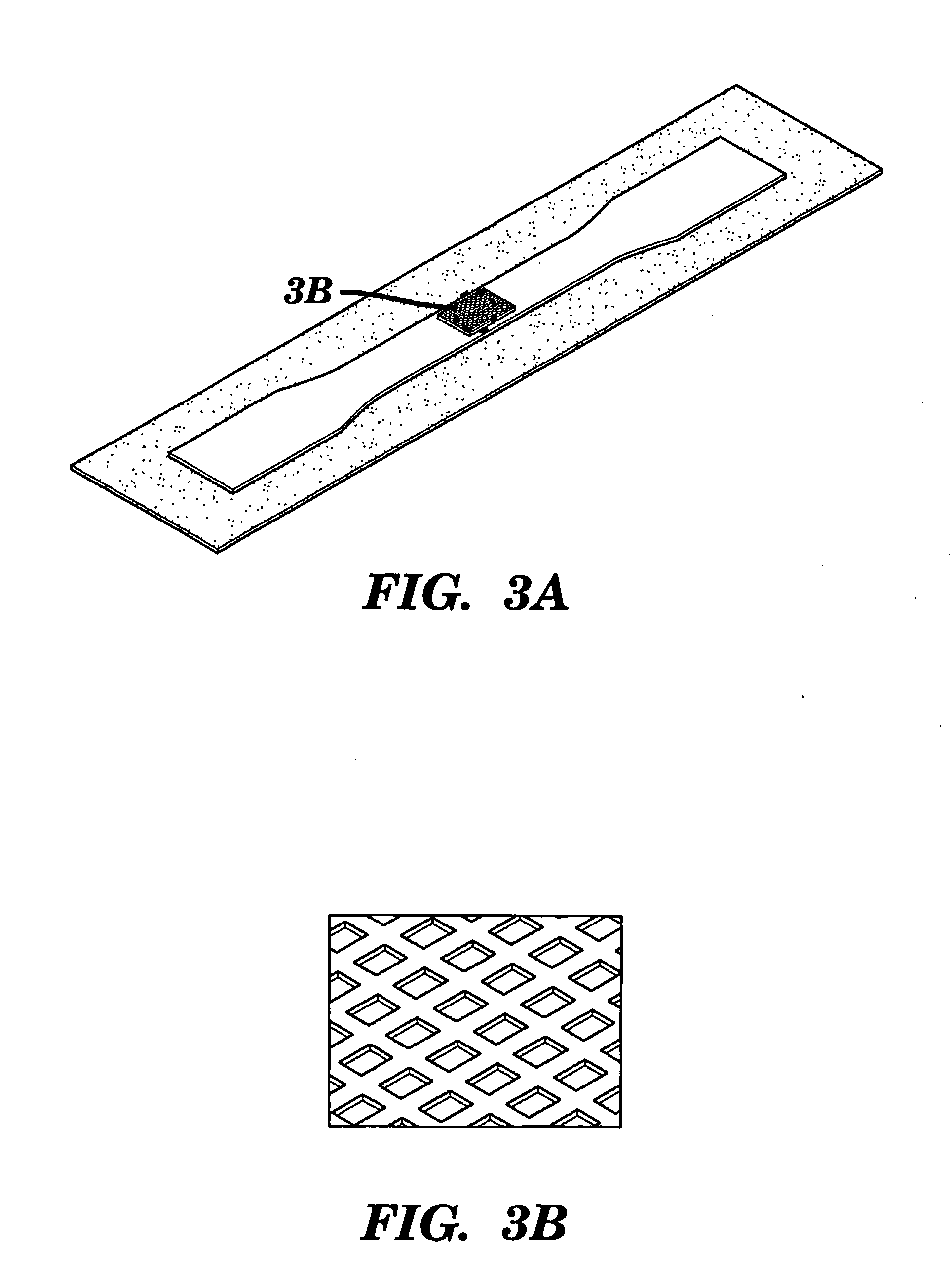
[0086]A simpler process in developing a silicon master dog-bone with embedded, grid pattern is described that can be used material such as PLGA. The Bio-LOM processing steps after section 1.3.1.2 are to remain the same. In the new process, a single photolithographic mask of the desired complete pattern for each layer is made with the dog-bone shape instead of embedding the smaller square sections. This allows for less user-error in the process. A number of dog-bones with etched pattern can be fabricated on a wafer (see FIG. 13).

2.2 Experimental Method for Growth and Testing

[0087]The well-defined scaffolds are characterized, introduced to chondrocytes and appropriate media, and then analyzed chemically and mechanically.

2.2.1. Characterization

[0088]Scanning Electron Microscopy (SEM). Zeiss DSM 940A is used to study the surface morphology of the materials before and after chondrocyte growth. Phase-contrast m...


PUM

PropertyMeasurementUnit
temperatureaaaaaaaaaa
vertical depthaaaaaaaaaa
temperatureaaaaaaaaaa

Abstract

The present invention provides a multilayer scaffold for tissue engineering. The scaffold comprises at least a first layer comprised of a polymer having a pattern of microchannels therein; and at least a second layer comprised of a polymer having a pattern of microchannels therein. The first and second layers are joined together (preferably by lamination) and the channels are connected for the circulation of fluid through the layers. The scaffold is coated with bacterial cellulose. The scaffold may further include a mammalian cell.

Description

CROSS REFERENCED APPLICATIONS[0001]This application claims the benefit under 35 U.S.C. §119(e) of U.S. provisional Patent Application No. 60 / 617,919, filed Oct. 12, 2004.FIELD OF THE INVENTION[0002]The present invention relates to multi-layered scaffolds for tissue engineering that comprise layers of polymer having a defined pattern of microchannels allowing for circulation of fluid throughout the layers and which are coated with bacterial cellulose to support the growth of cells. Methods for preparing these multi-layered scaffolds are also provided.BACKGROUND OF THE INVENTION[0003]Tissue engineering is a growing research area that has had numerous advances in understanding the cellular and tissue responses to artificial 2D and 3D scaffolds. However, the 3D scaffolds are typically ill-defined porous structures. Well defined 2D patterning is often explored through microcontact printing, self-assembled monolayers and similar experimental strategies, however, 2D systems are being recog...

Claims


Application Information

Patent Timeline
Patent Type & Authority Applications(United States)
IPC IPC(8): C12N5/00
CPCC12N5/0068C12N2533/30C12N2533/78C12N2535/10
Inventor KAPLAN, DAVID L.WONG, PETER Y.
Owner TRUSTEES OF TUFTS COLLEGE
Why Eureka
Try Eureka