Damascene reticle and method of manufacture thereof

a technology of etching cog and reticle, which is applied in the field of photolithographic reticle manufacturing methods, can solve the problems of etching cog reticles, affecting the image quality of etching cogs, and consuming the photoresist mask very quickly, so as to reduce the scattering of light, improve the imaging performance, and eliminate the growth of defects

Inactive Publication Date: 2008-11-20
GLOBALFOUNDRIES INC
View PDF7 Cites 5 Cited by
  • Summary
  • Abstract
  • Description
  • Claims
  • Application Information

AI Technical Summary

Benefits of technology

[0030]This invention leaves the top surface of a reticle which is completely planar, improving the imaging performance by reducing the scattering of light between features. Such a fully planar surface also allows the sealing of the top surface of the reticle without adverse effects, eliminating grow...

Problems solved by technology

There is a serious problem with the process of etching through the chrome of a COG reticle mask plate down to the quartz therebelow which is that the etching process for the chrome also consumes the photoresist mask very quickly which forces certain restrictions in the mask making process (e.g. resist thickness.)
There are other serious problems with etched COG reticles.
One such problem with etched COG reticles is that Electro-Static Discharge (ESD) can cause damage to the metal (chrome) pattern on a substrate composed of quartz as the insulating material.
The problem is that unwanted Electro-Static Discharge (ESD), involving rapid dissipation of electric charge in a short amount of time, often causes delamination of the chrome pattern from the quartz substrate.
That renders the mask defective so...

Method used


Image

  • Damascene reticle and method of manufacture thereof
  • Damascene reticle and method of manufacture thereof
  • Damascene reticle and method of manufacture thereof

Examples


first embodiment

of a Damascene Mask Plate Formed in a Transparent Reticle Mask Plate

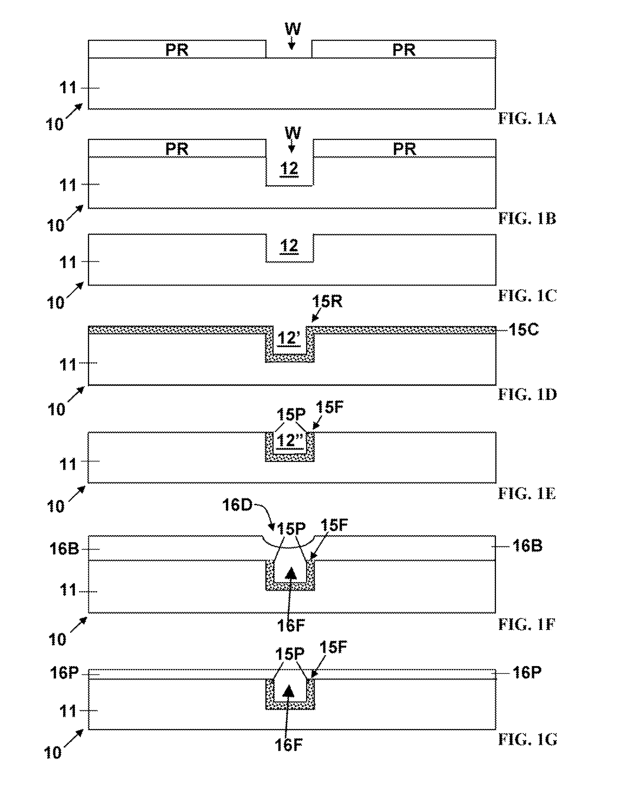
[0064]Heretofore, mask plate reticles have been formed by patterning opaque material on the top surface of a transparent substrate. In accordance with this invention a damascene mask plate is formed by first forming a pattern of recesses in a blank, transparent, reticle mask plate. Then the recesses are filled with opaque and / or partially transmissive materials depending upon which type of damascene mask plate is being formed in accordance with this invention. Several embodiments thereof are described below with reference to the appended drawings. The substrate can be selected to be transparent for an exposure radiation of an appropriate wavelength to be used with such mask plate reticles. FIGS. 1A-1F are schematic, elevational sections of a reticle 10 formed from a blank transparent reticle mask plate 11 (hereinafter mask plate 11). The process of manufacture provides a patterned damascene reticle 10 shown in FIG. ...

second embodiment

icle

[0075]FIGS. 3A-3F are schematic elevational views of a damascene PSM reticle 30 during the process of manufacture of the reticle in accordance with another aspect of the method of this invention, as shown by the flow chart of FIG. 4. FIGS. 3A-3F illustrate process flow for patterning the reticle 30. As shown in FIG. 3F, the resulting reticle 30 has PSM features 36F′ which are composed of deposited conformal film elements 33P / 35P filling a feature recess 32 in a mask plate 31. The reticle 30 is adapted to be used to expose patterns on a workpiece (not shown.) FIG. 3F shows a patterned reticle 30 which is to be employed as a PSM mask after the manufacture thereof in accordance with this invention for exposing patterns formed thereon.

[0076]FIG. 3A shows the reticle 30 in an initial, stage of processing in accordance with step A in FIG. 4. A transparent reticle mask plate 31 (hereinafter mask plate 31) is shown with a top surface on which a photoresist mask PR is formed. As with FIG...

third embodiment

ticle In-Situ Lens Formation on the Reticle

[0084]In a modification of the embodiment of FIG. 3F, aside from the detail that the shape and index of refraction of the outer, partially-transmissive, remainder element 33P is tuned so that parallel focused light beams come out of the top side of the reticle 30 as illumination is to be projected from below for all images. Improvements can employ multiple different layers with varying refraction indexes to improve the focus effect.


PUM


Abstract

A method for manufacturing an optical projection reticle employs a damascene process. First feature recesses are etched into a projection reticle mask plate which is transmissive or transparent. Then feature recesses are tilled with a radiation transmissivity modifying material comprising a partially transmissive material and/or a radiation absorber for absorbing actinic radiation. Sacrificial materials may be added to the recess temporarily prior to filling the recess to provide gaps juxtaposed with the material filling the recess. Thereafter, the sacrificial materials are removed. Then the projection mask is planarized leaving feature recesses filled with transmissivity modifying material, and any gaps desired. The projection mask is planarized while retained in a fixture holding it in place during polishing with a polishing tool and a slurry.

Description

BACKGROUND OF THE INVENTION[0001]The present invention relates to methods of manufacture of photolithographic reticles, i.e. masks, and reticles produced thereby. More particularly this invention relates to methods for fabrication of reticles for exposure of microelectronic integrated circuits and other micro-scale devices and to the reticles produced thereby.[0002]During the process of manufacturing of microelectronic integrated circuits on a substrate comprising a workpiece such as a semiconductor wafer or the like, layers of material on the workpiece are patterned photolithographically. A layer of a radiation sensitive resist (hereinafter resist) is deposited on the workpiece. The resist (e.g. photoresist) comprises a radiation sensitive material which can be exposed to a master image projected as patterns of radiation, e.g. light, ultraviolet light, x-ray, electron beam, or other forms of radiation. The resist is later exposed using an exposure tool, and a reticle. The reticle c...

Claims


Application Information

Patent Timeline
IPC IPC(8): G03F1/00C09K3/14
CPCG03F1/14G03F1/00G03F1/26G03F1/144G03F1/50
Inventor PETRARCA, KEVIN S.CANAPERI, DONALD F.KRISHNAN, MAHADEVAIYERMIH, REBECCA D.STEEN, STEVENGRABARZ, HENRYHIBBS, MICHAEL S.
Owner GLOBALFOUNDRIES INC
Why Eureka
Try Eureka