Thermally Controlled External Cavity Tuneable Laser

a tuneable laser and external cavity technology, applied in the direction of lasers, lasers, semiconductor lasers, etc., can solve the problems of spatial loss, reduced output power of transmitters, and inaccurate positioning of tuneable elements associated with transmitter lasers over the entire tuning and operating temperature range, so as to reduce misalignment, minimise misalignment, and reduce thermal expansion coefficient.

Active Publication Date: 2008-12-04
GOOGLE LLC
View PDF16 Cites 37 Cited by
  • Summary
  • Abstract
  • Description
  • Claims
  • Application Information

AI Technical Summary

Benefits of technology

[0026]A low thermal expansion coefficient for the materials making the supporting structures for optical elements aligned to the laser beam is desirable to minimise the misalignments due to thermal fluctuations, which may occur at a small scale in a laser package also when a TEC is used to stabilise the temperature.
[0027]Applicants have observed that thermal contact between the tuneable mirror and the thermally conductive platform would be considerably inhibited if a supporting member having a low thermal conductivity (e.g., made of a material suitable for laser welding) is placed in between the mirror and the platform. They have remarked that temperature stabilisation of the tuneable mirror is crucial, especially in case of tuneable mirror including a liquid crystal, as the properties of the liquid crystal may change due to thermal fluctuations. Preferably, thermal fluctuations in the tuneable mirror should not exceed 0.5° C. in a temperature range from −10 to 70° C. in o

Problems solved by technology

As DWDM uses narrower channel spacing, accuracy and control in the positioning of the tuneable elements associated with the transmitter lasers over the entire tuning and operating temperature range has become an important issue.
Non optimal positioning of tuneable elements results in spatial losses and reduced output power of the transmitter.
Spatial misalignments of optical components of the laser device may arise from temperature variations due to expansions and contractions associated to the various compo

Method used


Image

  • Thermally Controlled External Cavity Tuneable Laser
  • Thermally Controlled External Cavity Tuneable Laser
  • Thermally Controlled External Cavity Tuneable Laser

Examples


second embodiment

[0071]FIG. 3 is a schematic illustration of a laser assembly according to a second preferred embodiment of the present invention. The laser assembly 30 comprises a gain medium 31, a collimating lens 32, a FP etalon 33, a deflector 34 and a tuneable mirror 35. The gain medium 31 is based on a semiconductor diode, which comprises a back facet 41 and a front facet 42. The diode's front facet 42 is anti-reflection coated, whereas the back facet 41 is party reflective. Preferably, the gain medium is a semiconductor gain chip with a gain chip waveguide that is bent so that it has an angled incidence on the front facet in order to further reduce back reflections. The deflector of the folded laser cavity according to this second embodiment is a beam splitter (BS) 34. The light emitted from the gain medium 31 is collimated by collimating lens 32 and passes through the FP etalon 33. After having passed through the FP etalon, light travelling along optical path 37 impinges the BS 34, where it ...

third embodiment

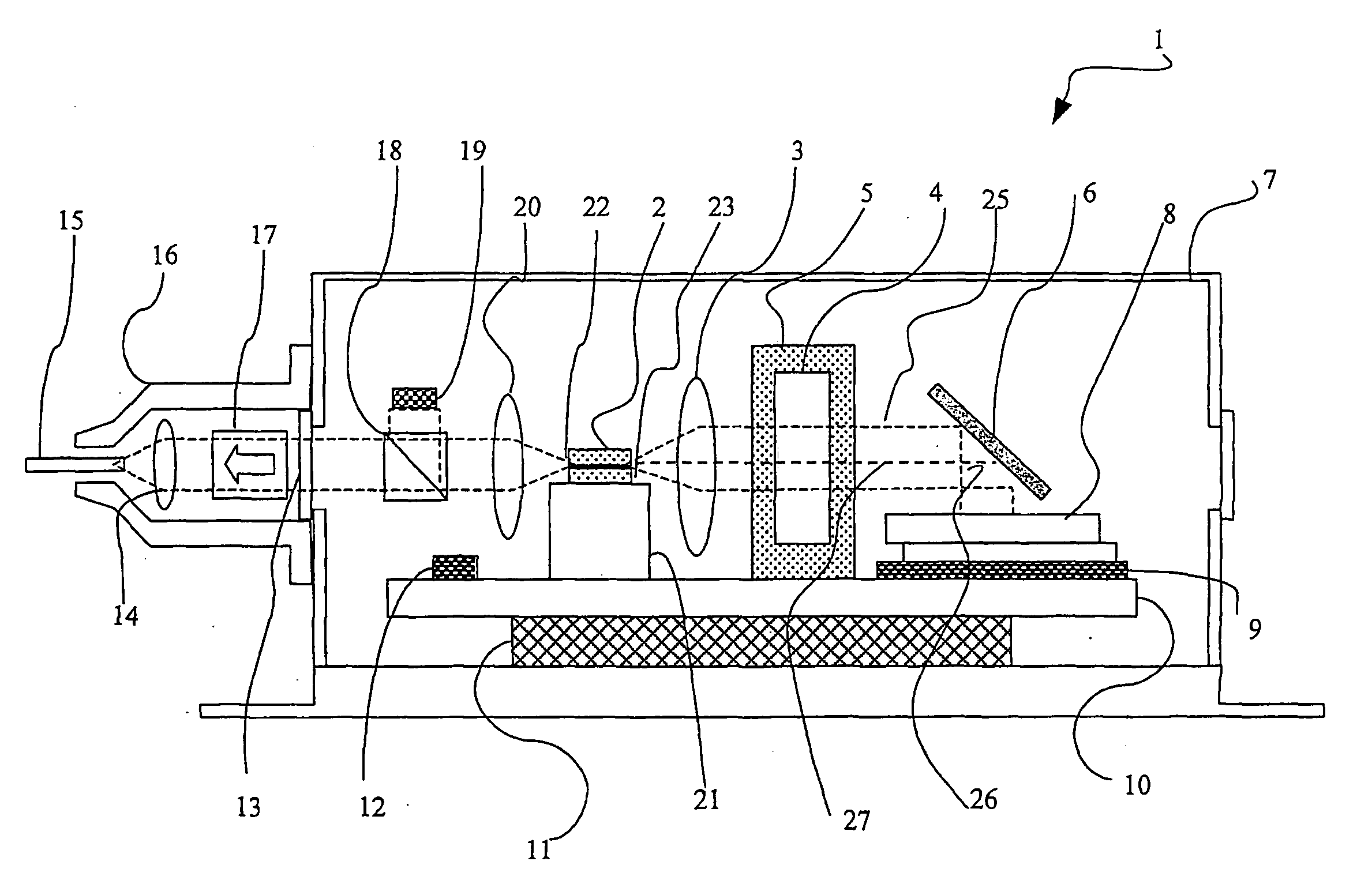
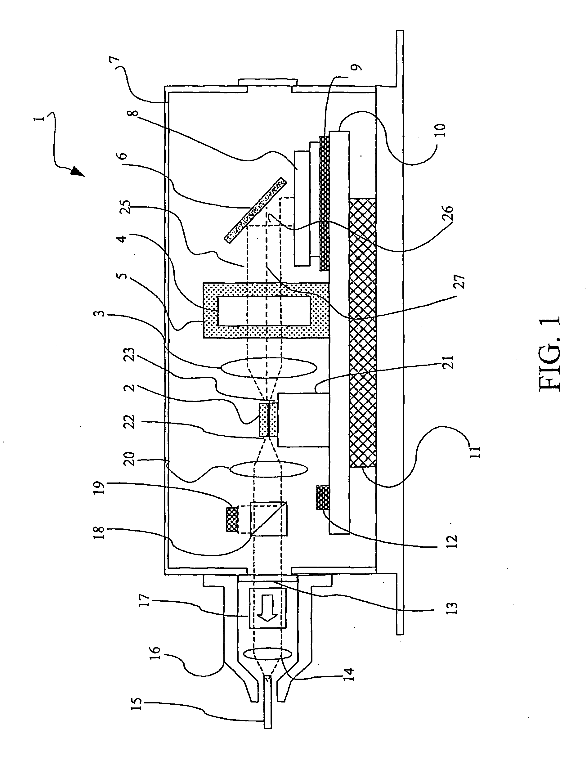
[0076]FIG. 4 illustrates a laser system according to the present invention. The same reference numerals are given to elements of the tuneable laser corresponding to those shown in FIG. 1 and their detailed explanation will be omitted.

[0077]After having passed through the FP etalon 4, light impinges on the beam splitter (BS) 45, where it is partially diverted to the tuneable mirror 8. A photodetector 46 receives the portion of the laser light, which has been returned by the tuneable mirror to the BS and then transmitted through the BS, as test beam for power monitoring.

[0078]The laser light transmitted through the BS 45 along the direction of the optical axis of the laser beam, i.e., the laser output beam, is directed through optical isolator 17 and then focussed by lens 14 into an optical fibre 15. It is important to note that the design of the laser cavity according to the embodiment of FIG. 4 has the advantage of improving the compactness of the cavity as a second collimating lens...


PUM


Abstract

The present invention relates to an external-cavity tuneable laser including a gain medium (2) and a tuneable mirror (8), wherein at least the tuneable mirror is in thermal contact, with a thermally conductive platform (10). The tuneable mirror lays substantially horizontally on the thermally conductive platform significantly thereby improving the thermal contact of the tuneable mirror with the platform. The laser beam from the gain medium is directed onto the tuneable mirror, which is mounted substantially horizontally with respect to the thermally conductive platform, by means of a deflector (6) that deflects the beam or a large part of it towards one of the principal surfaces of the tuneable mirror. The resulting laser cavity is therefore a folded cavity. The thermally conductive platform is preferably thermally coupled to a TEC (11) that provides thermal control for the platform. In a preferred embodiment, the deflector is a beam splitter that deflects part of the incoming light and transmits the remaining part. A beam splitter as deflector a more compact laser assembly can be envisaged. According to a preferred embodiment of the invention, the portion of light transmitted through the beam splitter forms the output laser beam. In other words, the external-cavity laser outputs a laser beam on the side of the wavelength selective elements (the tuneable mirror and, if any, the channel grid), i.e., on the side of the front facet of the laser diode. With this laser design, a collimating lens to collimate the output laser beam is not necessary.

Description

[0001]The invention concerns an external-cavity tuneable laser especially adapted for wavelength-division multiplexed optical communication networks.RELATED ART[0002]The use of lasers as tuneable light source can greatly improve the re-configurability of wavelength-division multiplexed (WDM) systems or of the newly evolved dense WDM (DWDM) systems. For example, different channels can be assigned to a node by simply tuning the wavelength. Also, tuneable lasers can be used to form virtual private networks based on wavelength routing, i.e., photonic networks.[0003]Different approaches can be used to provide tuneable lasers, such as distributed Bragg reflector lasers, VCSEL lasers with a mobile top mirror, or external-cavity diode lasers. External-cavity tuneable lasers offer several advantages, such as high output power, wide tuning range, good side mode suppression and narrow linewidth. Various laser tuning mechanisms have been developed to provide external-cavity wavelength selection...

Claims


Application Information

Patent Timeline
IPC IPC(8): H01S3/10H01S3/04H01S5/14
CPCH01S3/105H01S3/1062H01S5/0064H01S5/02248H01S5/02284H01S5/02415H01S5/02438H01S5/02476H01S5/028H01S5/0654H01S5/0683H01S5/1039H01S5/141H01S5/02325H01S5/02251
Inventor ROSSI, GIACOMO ANTONIORAMPULLA, ALBERTO
Owner GOOGLE LLC
Why Eureka
Try Eureka