Method for Manufacturing Metal Components and Metal Component

a manufacturing method and metal technology, applied in the field of high-performance metal components, can solve the problems of not having a practical effect on the component properties, achieving significant cost benefits, and reducing production costs, so as to improve weldability, improve machinability, and improve the effect of toughness

Inactive Publication Date: 2008-12-04
VALTION TEKNILLINEN TUTKIMUSKESKUS
View PDF3 Cites 7 Cited by
  • Summary
  • Abstract
  • Description
  • Claims
  • Application Information

AI Technical Summary

Benefits of technology

[0019]Particularly, according to the further actions needed to be performed to the second layer, the microstructure of the second layer provides pre...

Problems solved by technology

However, it has no practical effect on the component properties.
In addition, the first layer possibly consisting of very expensive special metal c...

Method used


Image

  • Method for Manufacturing Metal Components and Metal Component
  • Method for Manufacturing Metal Components and Metal Component

Examples


Embodiment Construction

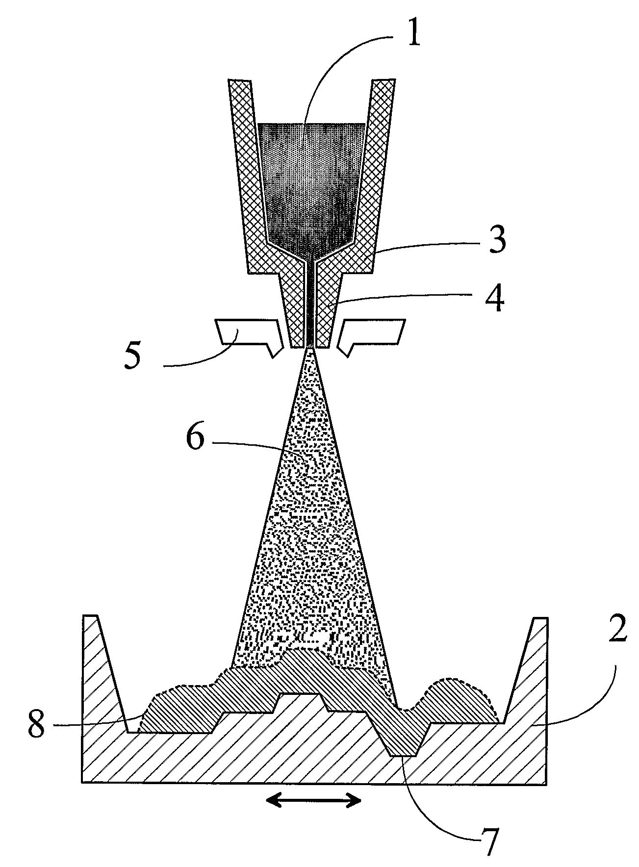
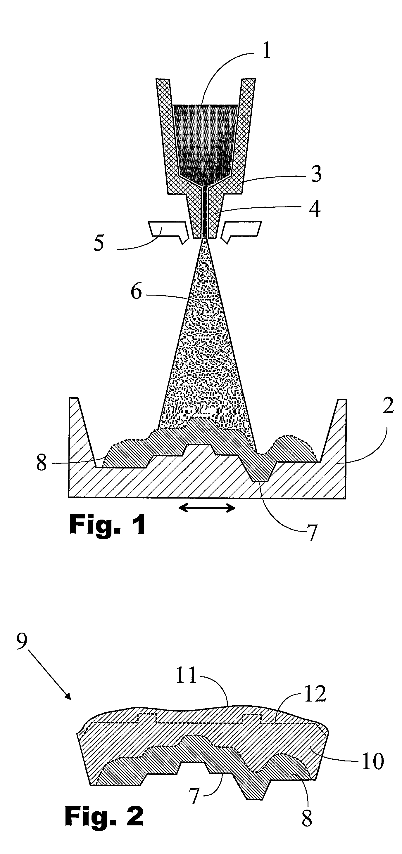
[0023]The arrangement of FIG. 1 illustrates the method of spray forming metal components with cooling channels. Molten metal 1 to be sprayed onto a ceramic mould 2 is fed from a heated reservoir 3 through a nozzle 4 and an atomizer 5 where metal is mixed to cool inert gas resulting in a spray 6 of rapidly cooling metal droplets directed to the mould. At the mould 2 the metal is grown with fine and homogenous microstructure producing a near net-shape component surface 7. The mould 2 is movable horizontally with respect to the nozzle 4 for covering by the spray 6 the whole mould area. After deposition of a first layer 8, another molten metal can be inserted in the reservoir for depositing a second layer on the first one having a different microstructure. Naturally, it is also possible to use separate reservoirs (not shown in the figure) and different nozzles for deposition of different layers.

[0024]FIG. 2 shows a cross section of a functionally layered metal component 9 made by a spra...


PUM

PropertyMeasurementUnit
Microstructureaaaaaaaaaa
Toughnessaaaaaaaaaa
Thermal conductivityaaaaaaaaaa

Abstract

A method for manufacturing metal components (9) by spray forming comprises depositing by spray forming a first layer (8) of a first metal on a mould, and depositing by spray forming a second layer (10) of a second metal on the first layer, wherein the materials to be deposited and the process conditions of the deposition are selected to produce the microstructure of the first layer (8) being optimised for the final use of the first layer surface (7) defined by the mould (2) on which the first layer is deposited, and the microstructure of the second layer (10) differing from that of the first layer and being optimised for the further actions to be performed to the second layer.

Description

FIELD OF THE INVENTION[0001]The present invention relates to high-performance metal components like die inserts and different kinds of tool parts, and to manufacturing thereof by spray forming technique.BACKGROUND OF THE INVENTION[0002]There are many high-performance metal components like die inserts, engine parts and tool heads which necessitate very time consuming and costly production processes due to the extremely severe working conditions. Such components are usually exposed to heavy mechanical and thermal cyclical stresses, mechanical wear and erosion and / or corrosion which all impose special requirements on the material of the component. These together with the complexity of geometry often needed makes the manufacturing processes very challenging. Thus, there is a continuous need for ways to improve the quality of such components and for cutting down the costs and long lead times.[0003]Powder metallurgy is one possible way to make high quality metal materials, but the costs a...

Claims


Application Information

Patent Timeline
IPC IPC(8): B32B15/01B22D23/00B22DC23C4/02C23C4/18
CPCB22F3/115B22F2998/00C23C4/02Y10T428/12493C23C4/185Y10T428/12986B22F5/007
Inventor YANG, YUNFENG
Owner VALTION TEKNILLINEN TUTKIMUSKESKUS
Why Eureka
Try Eureka