Two dimensional optical scanning image system

a scanning image and two-dimensional technology, applied in the field of optical scanning, can solve the problems of adversely affecting the fineness of detail, the diameter of currently available flexible endoscopes cannot be reduced to smaller than the image size, and the trade-off between high image quality and small size, and achieve sensitive and accurate methods to capture high-resolution images. , the effect of reducing the associated drawbacks

Inactive Publication Date: 2008-12-11
UNIV OF WASHINGTON
View PDF9 Cites 29 Cited by
  • Summary
  • Abstract
  • Description
  • Claims
  • Application Information

AI Technical Summary

Benefits of technology

[0010]Embodiments of the present invention are directed to a two-dimensional optical image scanner that eliminates drawbacks associated with traditional imaging systems. In embodiments of the present invention, the bundle of optical fibers and cameras are eliminated. The scanner offers a sensitive and accurate method to capture high-resolution images of physical and biological tissues. The minute physical size of such an electro-optical imaging system also offers a much needed advantage over conventional imaging systems. Embodiments may provide clinical endoscopic imaging and low cost optical scanners that are only a few millimeters long and that fit inside endoscopic tubes with diameters of less than one mm and tip deflection capability of ninety degrees in some embodiments and up to 360 degrees in other embodiments. This size will enable users to examine areas anatomically inaccessible by currently designed endoscopes, reduce collateral damage to tissue, and enable integration of imaging with other functional devices, such as therapy and diagnostic devices, for example.

Problems solved by technology

Many commercially available endoscopes suffer from a fundamental tradeoff between high image quality and small size, however.
For example, the diameter of currently available flexible endoscopes cannot be reduced to smaller than the image size.
Larger diameters adversely affect the fineness of detail that can be distinguished in an image or resolution.
Larger diameters also adversely affect the area that is visible through the endoscope or field of view (FOV).
Currently available endoscopes also suffer from poor control mechanisms.
Although these systems actuate the fiber, such systems cannot precisely control the position of the fiber tip without adding material to the fiber scan system and increasing the diameter and / or tip length.
However, near-field systems have a very limited field of view (e.g., typically less than 500 nanometers), and a light-emitting tip must be positioned within nanometers of the target.
A near-field system may be useful for imaging individual cells or molecules, but is not suitable for most medical procedures and other dynamic applications, which require a field of view of at least a micron and can not be dependant on precisely positioning a tip within nanometers of a target.
Using larger wavelengths to provide a suitable field of view with a near-field system would still require a substantially larger imaging system, which could not be integrated into a multi-function instrument.
However, the extremely low efficiency of light collection (into the core diameter, typically few microns) of this design remains a disadvantage.
Furthermore, confocal systems are limited to single wavelength operation, which does not enable color imaging or display.

Method used


Image

  • Two dimensional optical scanning image system
  • Two dimensional optical scanning image system
  • Two dimensional optical scanning image system

Examples


Embodiment Construction

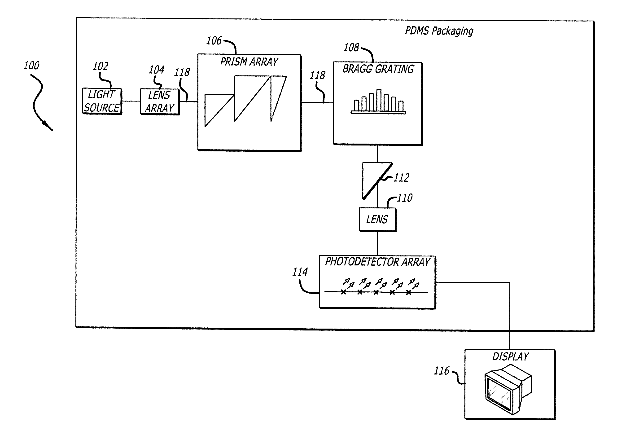
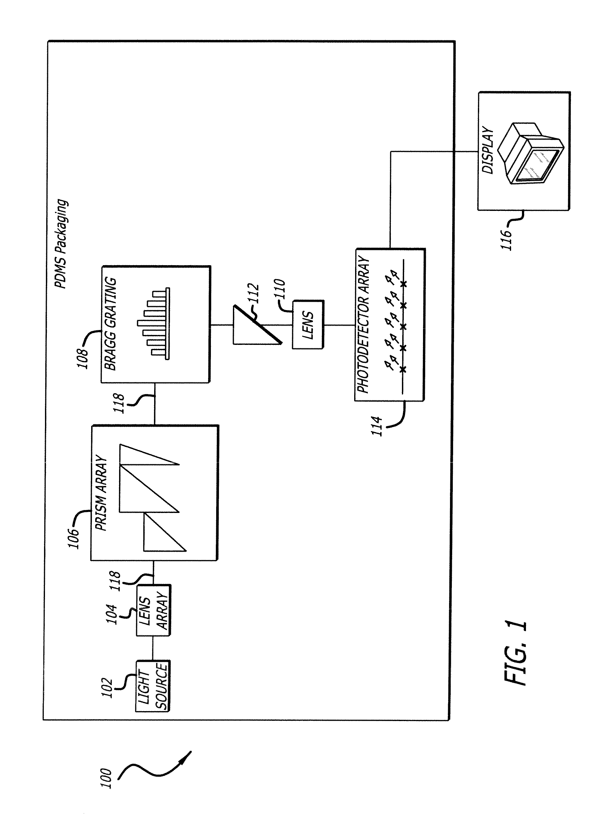
[0049]FIG. 1 is a block diagram of an electro-optic scanner 100 according to an embodiment of the present invention. In the illustrated embodiment, the scanner 100 includes a light source 102 coupled to a lens array 104. The lens array 104 is coupled to a prism array 106, which is coupled to a Bragg grating 108. The Bragg grating 108 is optionally coupled to a prism 112, which is optionally coupled to a spherical lens 110. The Bragg grating 108 also may be coupled to a photodetector array 114 without going through the lens 110 and / or the prism 112. The photodetector array 114 is coupled to a display 116. Also in the illustrated embodiment, the light source 102, lens array 104, prism array 106, Bragg grating 108, lens 110, prism 112, and photodetector array 114 are packaged in a biocompatible material such as silicone rubber, dimethicone and / or polydimethylsiloxane (PDMS). Alternatively, the light source 102, lens array 104, prism array 106, Bragg grating 108, lens 110, prism 112, an...


PUM


Abstract

An ultra high speed miniature two dimensional electro-optic image acquisition system uses prisms of varying geometries to control the amount of horizontal deflection and a Bragg grating to control the amount of vertical deflection. A collimating lens array and a Gaussian profile Bragg grating help confine the beam diameter of the deflected light beam. A separate prism further bends light into the vertical direction. A spherical lens focuses light onto a photodetector array for display.

Description

BACKGROUND[0001]1. Field[0002]Embodiments of the present invention relate to optics and, in particular, to image scanning.[0003]2. Discussion of Related Art[0004]Flexible endoscopes are commonly used in medical applications to look inside the human body to check the status of such organs as lungs, intestines, and colon, for example. Presently available flexible scope designs use either a bundle of optical fibers, typically in a tube, and / or one or more cameras having an array of detectors to capture an image.[0005]Many commercially available endoscopes suffer from a fundamental tradeoff between high image quality and small size, however. For example, the diameter of currently available flexible endoscopes cannot be reduced to smaller than the image size. The diameter also is limited by the individual pixel size of a camera or by the diameter of optical fibers used to acquire the image. Currently, the smallest pixel element is determined by the size of the end of an optical fiber, wh...

Claims


Application Information

Patent Timeline
Patent Type & Authority Applications(United States)
IPC IPC(8): G02B26/10G02B5/18
CPCA61B1/00183G02B5/04G02B6/124G02B6/34
Inventor WANG, WEI-CHIHREINHALL, PER G.
Owner UNIV OF WASHINGTON
Why Eureka
Try Eureka