Sample Preparation for Micro-Analysis

a micro-analysis and sample technology, applied in the field of sample preparation techniques and procedures, can solve the problems of sample features distortion, sample containing water-originating contaminants or artifacts, sample swelling, etc., and achieve the effect of reducing size (surface area dimensions) and preventing or minimizing the occurrence of vibration

Inactive Publication Date: 2008-12-18
CAMTEK LTD
View PDF21 Cites 29 Cited by
  • Summary
  • Abstract
  • Description
  • Claims
  • Application Information

AI Technical Summary

Benefits of technology

[0040]The present invention is a type of micro-analytical sample preparation technique which is based on sectioning or segmenting of at least a part of a material, such as that of a sample precursor, via reducing at least one dimension (length, width, or / and thickness, depth or height), of the size of the sample precursor, thereby producing a prepared sample ready for subjection to another process.
[0044]According to further characteristics in preferred embodiments of the invention described below, the sample preparation system optionally, further includes at least one additional main component selected from the group consisting of: (g) an adhering interface assembly, for enabling interfacing of (b) the transporting and positioning unit with (d) the picking and placing unit, for adhering a first component to a second component within the sample preparation system; (h) a pneumatics control unit, for controlling pneumatics of selected main components [(a) the sample precursor holding unit, (b) the transporting and positioning unit, (d) the picking and placing unit, and (f) the cryogenic sectioning unit] of the sample preparation system; (i) a sample precursor size (surface area dimensions) reducing unit, for reducing size (surface area dimensions) of the sample precursor to a pre-determined sample precursor size; (j) a scribing and cleaving unit, for generating a scribe line on a surface of the sample precursor, and cleaving the sample precursor along the scribe line; (k) a micro-mask adhering unit, for adhering a micro-mask onto a surface of the sample precursor; and (l) an anti-vibration unit, for preventing or minimizing occurrence of vibrations during operation of the system.
[0051]According to further characteristics in preferred embodiments of the invention described below, the method of preparing a sample for micro-analysis, optionally, further includes at least one additional main step (and components thereof) selected from the group consisting of: (g) adhering a first component to a second component within the sample preparation system, by an adhering interface assembly which enables interfacing of the transporting and positioning unit with the picking and placing unit; (h) controlling pneumatics of selected main components (a sample precursor holding unit, a transporting and positioning unit, a picking and placing unit, and a cryogenic sectioning unit) of the sample preparation system, by a pneumatics control unit; (i) reducing size (surface area dimensions) of the sample precursor to a pre-determined sample precursor size, by a sample precursor micro-size (surface area dimensions) reducing unit; (j) generating a scribe line on a surface of the sample precursor, and cleaving the sample precursor along the scribe line, by a scribing and cleaving unit; (k) marking a target area or region of interest (ROI) on a surface of the sample precursor, by a marking device; (l) adhering a macro-mask onto a surface of the sample precursor, by selected sample preparation system main components; (m) adhering a micro-mask onto a surface of the sample precursor, by a micro-mask adhering unit; and (n) preventing or minimizing occurrence of vibrations during operation of the sample preparation system, by an anti-vibration unit.

Problems solved by technology

A potentially significant limitation associated with water cooled sawing (wet sawing) types of sectioning procedures relates to the potentially undesirable presence of contaminants or artifacts in the water used for cooling the saw blade and the sample precursor during the sawing process, potentially resulting in samples containing the water originating contaminants or artifacts.
In addition, water (regardless of its purity level) is known for causing swelling of a sample, translating to distortion of sample features.
Such occurrences would most likely lead to erroneous results obtained during the eventual micro-analysis of the sample.
Regarding the type of sample precursor which is used for preparing a sectioned sample, three significant limitations exist in current practice.
First, a given prior art micro-analytical sample preparation sectioning procedure which is particularly suitable for sectioning (cutting, cleaving, slicing, or / and polishing) in specific directions along crystal boundaries or edges in a mono-crystalline type of sample precursor material, is ordinarily not suitable for sectioning a poly-crystalline or amorphous type of sample precursor material.
Second, prior art sample preparation sectioning procedures are ordinarily not sufficiently suitable for processing sample precursors having adjacent layers which poorly adhere to each other.
Third, prior art sample preparation sectioning procedures are ordinarily not sufficiently suitable for ‘in-line’ initial handling and processing of relatively large sample precursors, for example, a whole semiconductor wafer having a diameter of about 300 mm.
Regarding the type of the sectioned sample subsequently prepared, two significant limitations currently exist in practice.
This limitation reduces subsequent processing options one has regarding final preparation of a sectioned sample.
Second, prior art micro-analytical sample preparation sectioning procedures which are used for preparing samples that are subsequently subjected to ion beam milling types of final preparation techniques, currently produce sectioned samples having relatively large size dimensions that require proportionately large amounts of ion beam milling time.
As the time required for performing an ion beam milling procedure increases, there is an increase in the potential for introduction of contamination and artifacts to the sample, as a result of re-deposition during the ion beam milling process.
Such introduction of contamination and artifacts to a sample tends to interfere with the mass spectrometry, and analysis thereof, required during a typical micro-analytical technique.
Regarding the particular preparatory requirements of the micro-analytical technique which is ultimately used for analyzing a given sample, a significant limitation relates to the lack of generality of applicability of a given prior art micro-analytical sample preparation sectioning procedure.
However, typically, a given micro-analytical sample preparation sectioning procedure is preferably employed for the ultimate purpose of only one type of micro-analytical technique, that is, SEM, or TEM, or STEM, or EDS, or AFM, or SIMS, or GDS, respectively, and tends not to be equally generally applicable to more than one type of micro-analytical technique.
A result of this limitation is that a different micro-analytical sample preparation sectioning procedure, involving different methodology and associated equipment, needs to be employed for ultimate preparation of each specific type of micro-analytical sample.
Thus, the same limitation again arises in practice.
Another specific limitation which particularly characterizes prior art dimpling (polishing, grinding) procedures used in sectioning types of micro-analytical sample preparation techniques, is that such procedures are not applicable for preparing specific site (target) samples.
Another specific limitation which is particularly prevalent during application of prior art sawing procedures used in sectioning types of micro-analytical sample preparation techniques, including, for example, the cryogenic sawing (dry sawing) procedure disclosed by the present assignee / applicant and summarized hereinabove, is based on the practically unavoidable formation of undesirable micro-sized cracks or / and artifacts in the sample during the sawing process.

Method used


Image

  • Sample Preparation for Micro-Analysis
  • Sample Preparation for Micro-Analysis
  • Sample Preparation for Micro-Analysis

Examples


case 1

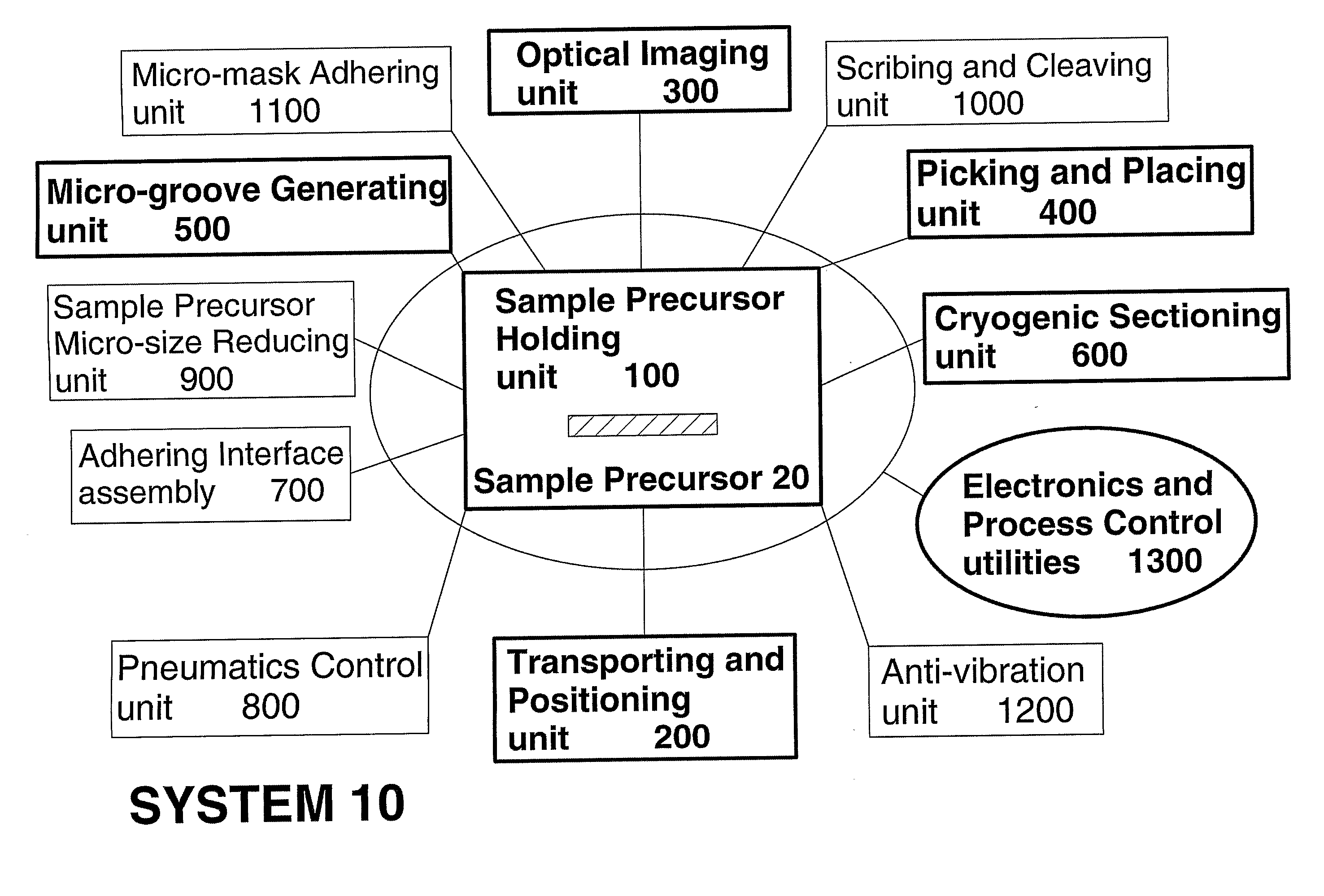
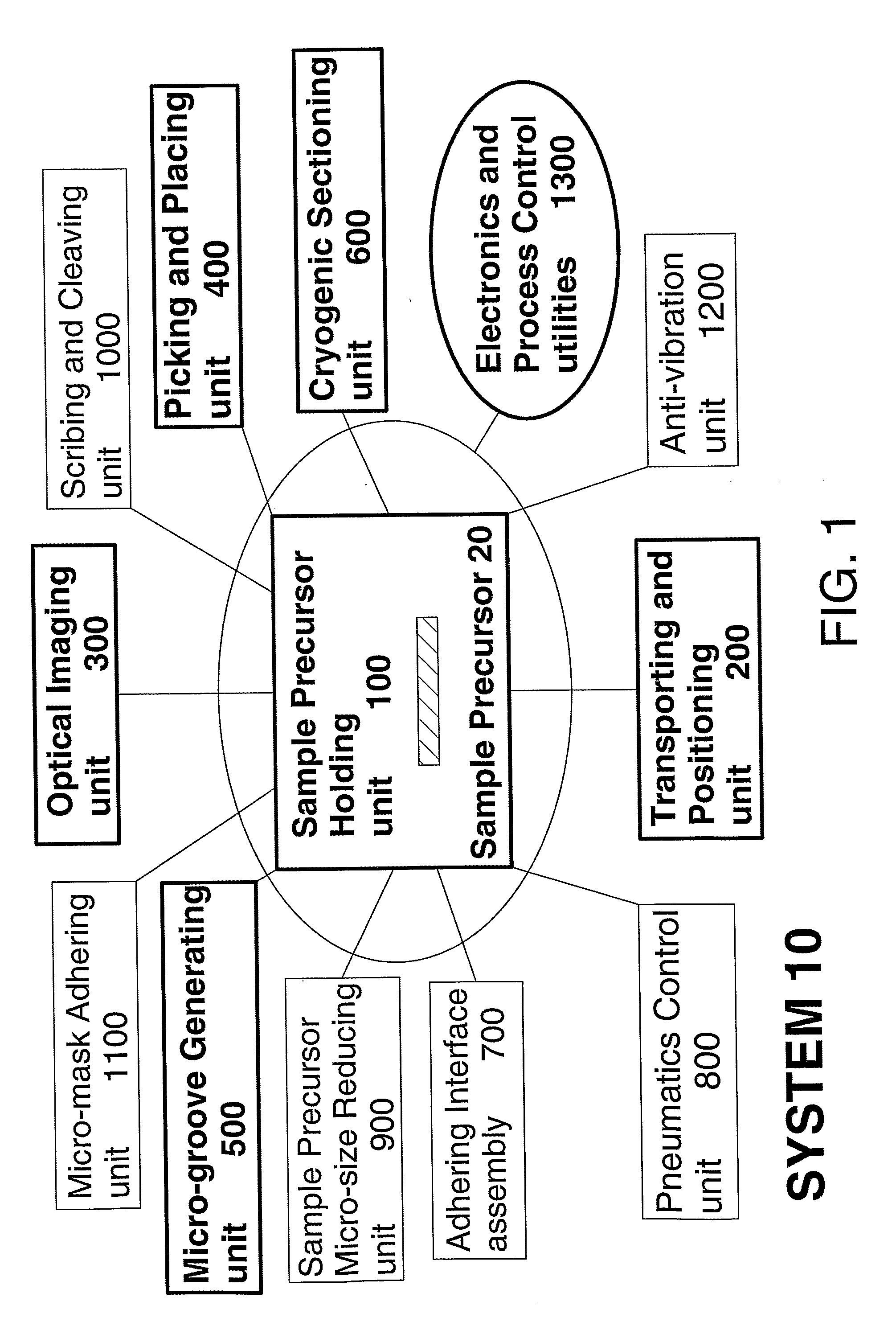
[0274] If the value of each surface area dimension, length and width, of the initially provided sample precursor 20 is in a first pre-determined range, for example, of less than a first pre-determined value (for example, about 3 mm), and larger than a second pre-determined value (for example, about 1 mm), then the initially provided sample precursor 20 is subjected to direct continuation of the method.

case 2

[0275] If the value of one or both surface area dimensions, length or / and width, of the initially provided sample precursor 20 is / are in a second pre-determined range, for example, of less than a third pre-determined value (for example, about 18 mm), and larger than the first pre-determined value (for example, about 3 mm), then the initially provided sample precursor 20 is subjected to a sample precursor size (surface area dimensions) reducing procedure, using the (preferably, automatic) sample precursor size (surface area dimensions) reducing unit 900, for reducing the value of the corresponding one or both surface area dimensions to be within the first pre-determined range (of case (1)), for forming the sample precursor 20 having a pre-determined size. Then the sample precursor 20 is subjected to continuation of the method.

case 3

[0276] If the value of one or both surface area dimensions, length or / and width, of the initially provided sample precursor 20 is / are equal to or larger than the third pre-determined value (of case (2)) (for example, about 18 mm), then the initially provided sample precursor 20 is first subjected to a macro-size optical inspection and marking, and is then subjected to a (manual) macro-size (surface area dimensions) reducing procedure, using optional sample precursor macro-size holding chuck 150 of sample precursor holding unit 100. Then, either Case 1 or Case 2 is performed.

[0277]Following sample precursor 20 being of an appropriate size, preferably, sample precursor 20 is manually mounted onto chuck base assembly 140, as shown in FIG. 3, via pneumatics control unit 800 (FIGS. 2 and 9A).

[0278]Step (a) includes loading of consumables or / and disposables, for example, sample precursor support structure 110 (side view) or 120 (planar view), or alternatively, the set of sample precursor ...


PUM


Abstract

System and method for preparing a sample for micro-analysis, comprising: (a) sample precursor holding unit, for supporting and holding a sample precursor; (b) transporting and positioning unit, for transporting and positioning the sample precursor holding unit; (c) optical imaging unit, for optically imaging, recognizing, and identifying, target features on the sample precursor, and for monitoring the sample preparation; (d) picking and placing unit, for picking and placing the sample precursor and system components from initial positions to other functionally dependent positions; (e) micro-groove generating unit, for generating at least one micro-groove in a surface of the sample precursor, wherein the micro-groove generating unit includes components for controlling formation of each micro-groove in the surface; and (f) cryogenic sectioning unit, for cryogenically sectioning the sample precursor to a pre-determined configuration and size, for forming the prepared sample. Optionally, includes a micro-mask adhering unit, and a macro-mask adhering method.

Description

FIELD AND BACKGROUND OF THE INVENTION[0001]The present invention relates to sample preparation techniques and procedures, particularly those used in the fields of semiconductor manufacturing, micro-analytical testing, and materials science, which are employed prior to subjecting samples, particularly of semiconductor wafers, to micro-analysis. More particularly, the present invention relates to a system and corresponding method of preparing a sample for micro-analysis.[0002]The present invention is a type of micro-analytical sample preparation technique which is based on ‘sectioning’ or ‘segmenting’ of at least a part of a material, such as that of a sample precursor, via reducing at least one dimension (length, width, or / and thickness, depth or height), of the size of the sample precursor, thereby producing a prepared sample ready for subjection to another process. Herein, the terms ‘sectioning’ and ‘segmenting’ are generally and equivalently referred to as ‘sectioning’, and genera...

Claims


Application Information

Patent Timeline
Patent Type & Authority Applications(United States)
IPC IPC(8): G01N1/28B32B38/00B32B38/10B32B37/06H01L21/00G01N1/34G01N1/04B28D5/00
CPCG01N1/286G01N1/32H01L21/67092Y10T83/929
Inventor BOGUSLAVSKY, DIMITRISMITH, COLINVIAZOVSKY, DANFARHANA, DANNYZACHARIN, DIMITRYARONOV, GRIGORI
Owner CAMTEK LTD
Why Eureka
Try Eureka