Optical component and method for its production

a technology of optical components and components, applied in the direction of glass tempering apparatus, nuclear engineering, laser details, etc., can solve the problems of difficult crystal material preparation, difficult to connect to glass optical fiber, difficult to process into desired shape, etc., to achieve excellent secondary optical non-linear properties, excellent shg (second harmonic generation) or electrooptical effects, and efficient heating

Inactive Publication Date: 2008-12-25
ASAHI GLASS CO LTD
View PDF11 Cites 7 Cited by
  • Summary
  • Abstract
  • Description
  • Claims
  • Application Information

AI Technical Summary

Benefits of technology

[0017]With the optical component of the present invention, glass containing a heat source material is employed, whereby an area around the portion irradiated with the laser beam is locally efficiently heated, whereby crystallization at the irradiated portion will be promoted to form a single crystal or a group of crystal grains composed solely of components constituting the glass matrix and not containing the heat source material. Such a single crystal or a group of crystal grains is excellent in secondary optical non-linear properties and forms a pattern excellent in SHG (second harmon

Problems solved by technology

On the other hand, an optical component such as an integrated optical switch using a non-linear optical single crystal such as LiNbO3 to utilize the secondary optical non-linear properties inherent to the crystal, has been proposed, but it is difficult to connect it to glass optical fiber.
Besides, preparation of the crystal material is difficult, and the shape-forming property is also inferior to a glass material, whereby it is very difficult to process it into a desired shape.
However, it does not essentially have a structure having an electrical polarity aligned (oriented) in a specific direction as in the case of a crystal material, and in principle, glass does not show secondary optical non-linear properties.
However, in such prior art, it was not possible to control the alignment of

Method used


Image

  • Optical component and method for its production
  • Optical component and method for its production
  • Optical component and method for its production

Examples


first embodiment

[0034]An optical component in the first embodiment employs, as a starting material, glass having at least one member selected from Ni, Fe, V and Cu incorporated to a glass matrix comprising at least one glass-forming oxide selected from SiO2, GeO2, B2O3, P2O5, TeO2, Ga2O3, V2O5, MoO3 and WO3 and at least one member selected from alkali metals, alkaline earth metals, rare earth elements and transition elements. Each glass-forming oxide has an effect to increase a glass forming ability, and alkali metals, alkaline earth metals, transition elements and rare earth elements have a function to increase the optical characteristics. Further, Ni, Fe, V and Cu will function as a medium to absorb a laser beam and convert it to heat i.e. as a heat source material and have an effect to self-organizingly form a single crystal or a group of crystal grains composed solely of components constituting the glass matrix at a temperature in the vicinity of the glass softening point at a portion irradiate...

second embodiment

[0043]An optical component in the second embodiment employs, as a starting material, glass having at least one member selected from V, Fe, Cr, Mn and Cu is incorporated as a heat source material to the same glass matrix as in the first embodiment.

[0044]And, in accordance with the following first process or second process, a pattern made of a single crystal or a group of crystal grains will be formed at the surface or the inside of the above glass.

First Process

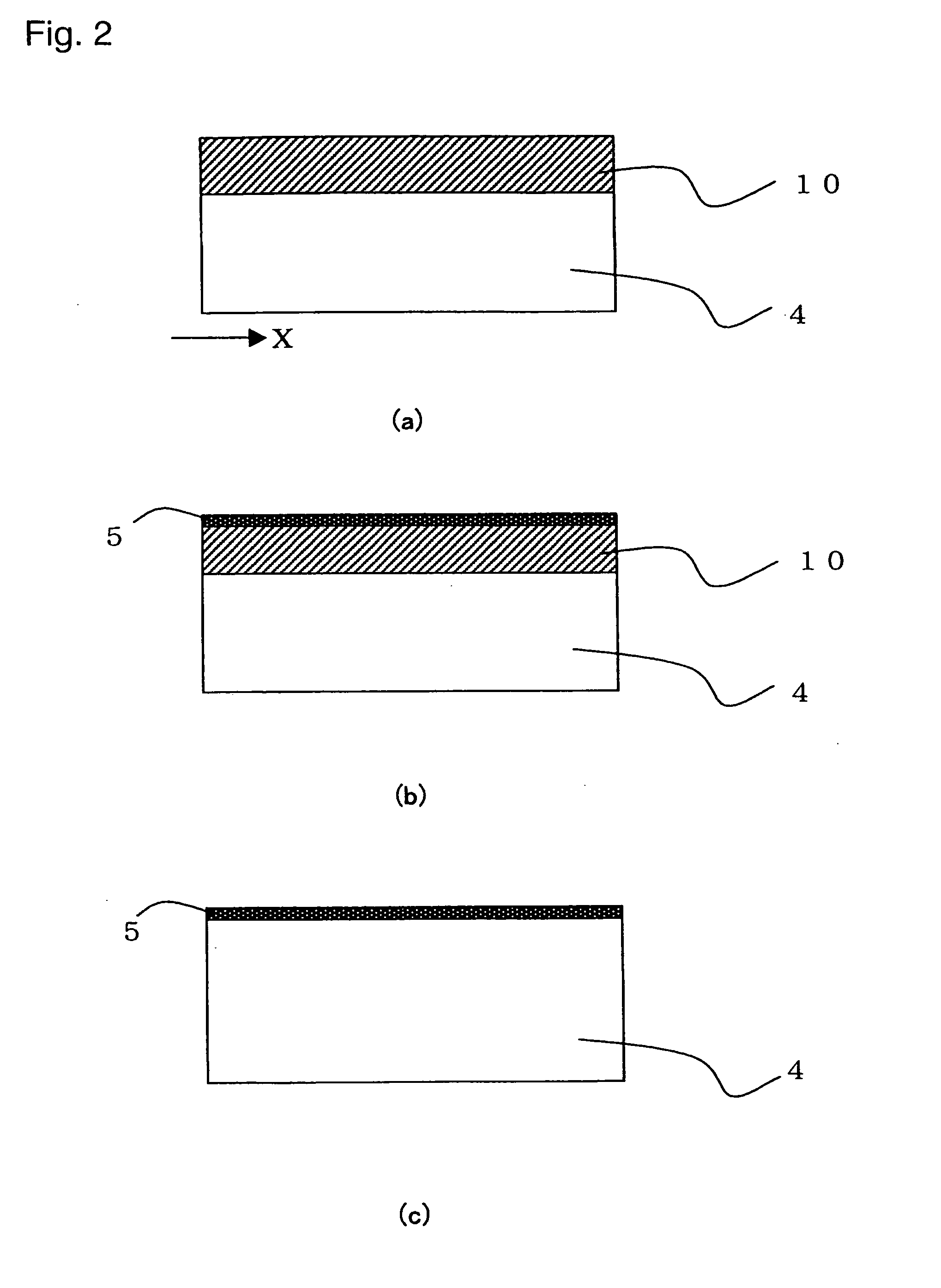
[0045]FIG. 2 is a schematic view illustrating the first process. Firstly, the glass is subjected to reduction treatment or oxidation treatment. By the reduction treatment or oxidation treatment, the ionic valency of the heat source element in the glass will be changed, whereby as shown in FIG. 2(a), a light-absorbing layer 10 having an absorption coefficient at an emission wavelength of a laser beam to be applied increased over a prescribed depth from the surface of the glass 4, will be formed. Here, the oxidation treatment may...

example 1

[0062]Glass comprising 1 mol % of NiO, 33.3 mol % of BaO, 16.7 mol % of TiO2 and 50 mol % of SiO2, was prepared by a melting method and formed into 10 mm×10 mm×1 mm, and further optical polishing was applied to the surface of 10 mm×10 mm as a surface to be irradiated with a laser. Here, the glass transition temperature of the glass was 743° C.

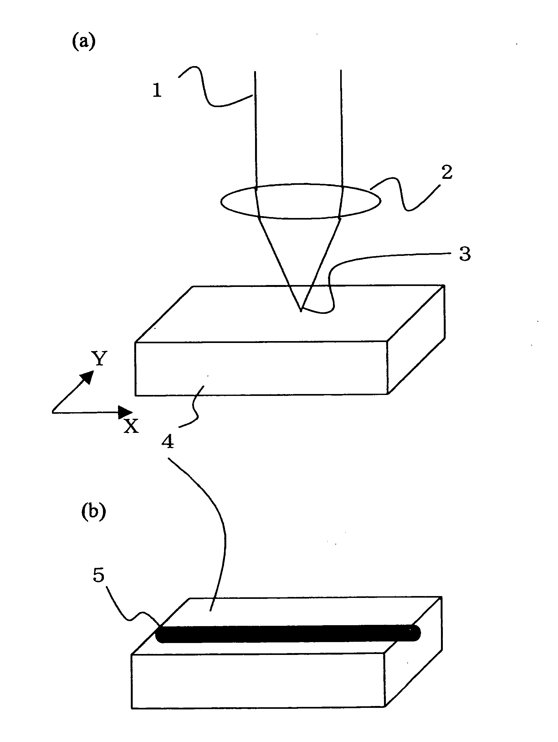
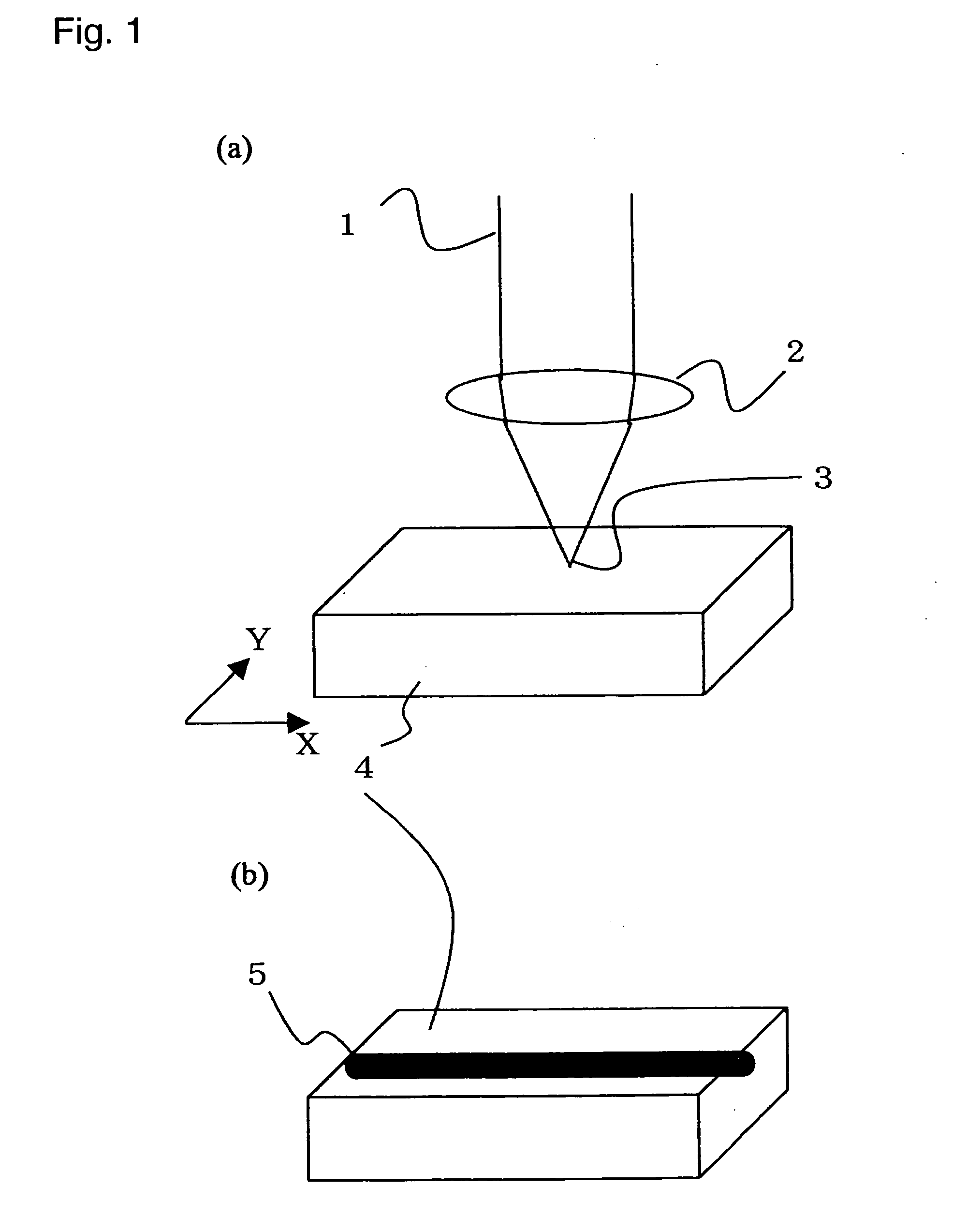
[0063]Then, using a laser irradiation apparatus shown in FIG. 1(a), light 1 of an Nd:YAG laser (wavelength: 1.06 μm) being CW laser was applied, with its focal point 3 adjusted to the polished surface of the glass 4 by means of the lens 2, so that the position of the focal point 3 of the laser beam was spatially moved continuously at a rate of 7 μm / sec in the X-direction with an irradiation power of 80 W / cm2, thereby to prepare a group 5 of crystal grains linearly grown as shown in FIG. 1(b). FIG. 5 shows a transmission polarization microscopic photograph of the laser-irradiated portion of the glass wherein Ba2TiSi2O8 crystal grains having grai...


PUM

PropertyMeasurementUnit
Diameteraaaaaaaaaa
Diameteraaaaaaaaaa
Speedaaaaaaaaaa

Abstract

To obtain an optical component having excellent secondary optical nonlinear properties by irradiating a surface and/or inside of glass having at least one member selected from Ni, Fe, V, Cu, Cr and Mn as a heat source material for absorbing and converting a laser beam to heat, incorporated to a glass matrix comprising at least one glass-forming oxide-selected from SiO2, GeO2, B2O3, P2O5, TeO2, Ga2O3, V2O5, MoO3 and WO3 and at least one member selected from alkali metals, alkaline earth metals, rare earth elements and transition elements, with a laser beam with a wavelength to be absorbed by the heat source material, to convert the irradiated portion to a single crystal or a group of crystal grains comprising components contained in the glass matrix and not containing the heat source material, thereby to form a pattern.

Description

TECHNICAL FIELD[0001]The present invention relates to a technique which comprises irradiating a surface and / or inside of glass with a laser beam to crystallize the irradiated portion to form a pattern at the surface and / or inside of the glass.BACKGROUND ART[0002]While being glass, crystallized glass has secondary optical non-linear properties inherent to crystal, and thus, it has a wide transmitting wavelength region, and it can be easily connected to glass optical fiber. Thus, it is expected as a new photonics material for an optical integrated circuit or an optical switch for light wave control.[0003]On the other hand, an optical component such as an integrated optical switch using a non-linear optical single crystal such as LiNbO3 to utilize the secondary optical non-linear properties inherent to the crystal, has been proposed, but it is difficult to connect it to glass optical fiber. Besides, preparation of the crystal material is difficult, and the shape-forming property is als...

Claims


Application Information

Patent Timeline
IPC IPC(8): A61N5/00H01S3/17
CPCC03C3/078C03C3/253C03C10/00C03C23/0025C03C2218/345G02B6/13G02F1/3551G02F1/377
Inventor KOMATSU, TAKAYUKIHONMA, TSUYOSHIFUJIWARA, TAKUMIBENINO, YASUHIKO
Owner ASAHI GLASS CO LTD
Why Eureka
Try Eureka