
Implantable Power Sources and Sensors

a technology of power sources and sensors, applied in the direction of peptides, other medical devices, intravenous devices, etc., can solve the problem of the number of microorganisms

Inactive Publication Date: 2008-12-25
GLUSENSE LTD
View PDF61 Cites 9 Cited by
  • Summary
  • Abstract
  • Description
  • Claims
  • Application Information

AI Technical Summary

Benefits of technology

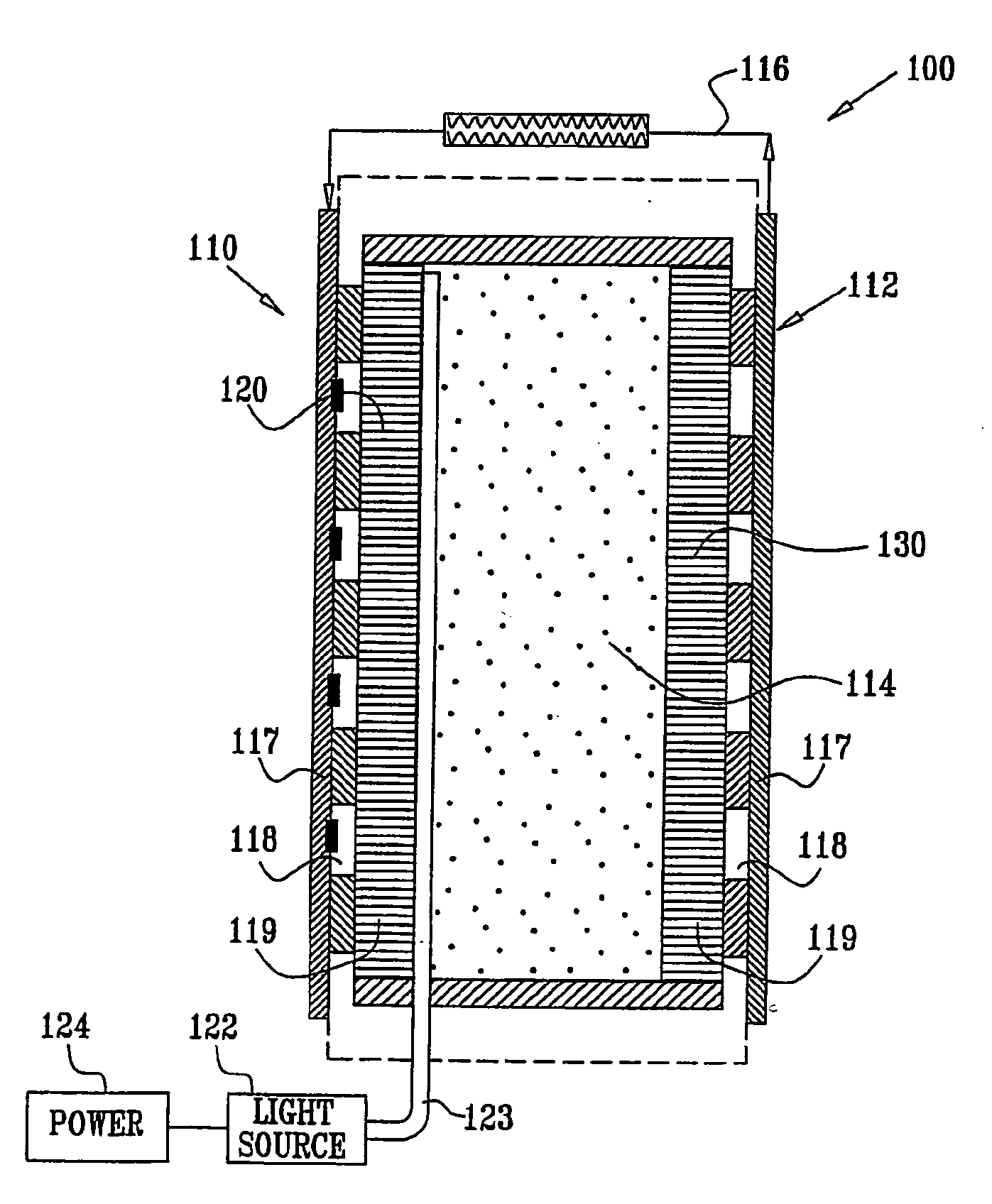
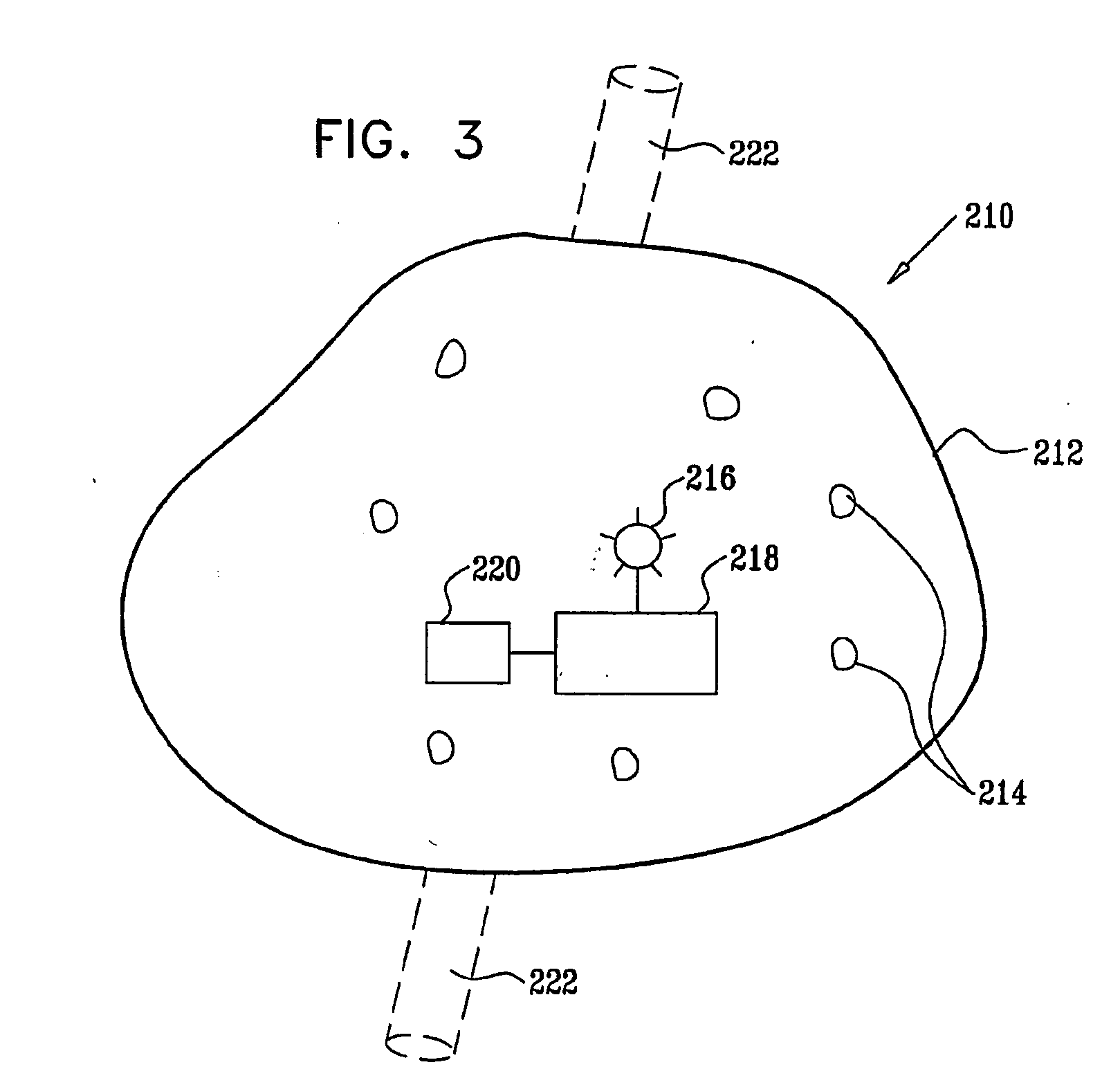
"The present invention is about a device that can determine the level of a substance in the blood or body fluid of a patient. The device includes a semi-permeable barrier that encases microorganisms and allows them to sense and respond to the specific substance. The microorganisms can be photosynthetic organisms that use photosynthesis to produce glucose and oxygen when exposed to light. The device can measure the changes in carbon dioxide and oxygen levels to determine the glucose level. The device can also contain other types of microorganisms, such as fungus, yeast, or bacteria, and can be used to detect other substances in the body. The device is implanted in the patient and is designed to isolate the microorganisms from the immune system, preventing them from causing infections or triggering immune responses. The device can also contain a matrix or other material to isolate the microorganisms from the body and support them in the device. The microorganisms can be photosynthetic or other types of organisms that use photosynthesis to produce glucose and oxygen. The device can be powered by a battery and can be controlled by a controller that pulses the light source on and off. The device can also measure the electrical conductivity across the membrane or the level of other chemicals in the body. Overall, the device provides a non-invasive and efficient way to measure the levels of various substances in the body."

Problems solved by technology

Additionally, the semi-permeable barrier provides a physical barrier limiting the number of microorganisms in the device due to the limited space inside the semi-permeable barrier.

Method used


Image

  • Implantable Power Sources and Sensors
  • Implantable Power Sources and Sensors
  • Implantable Power Sources and Sensors

Examples


Embodiment Construction

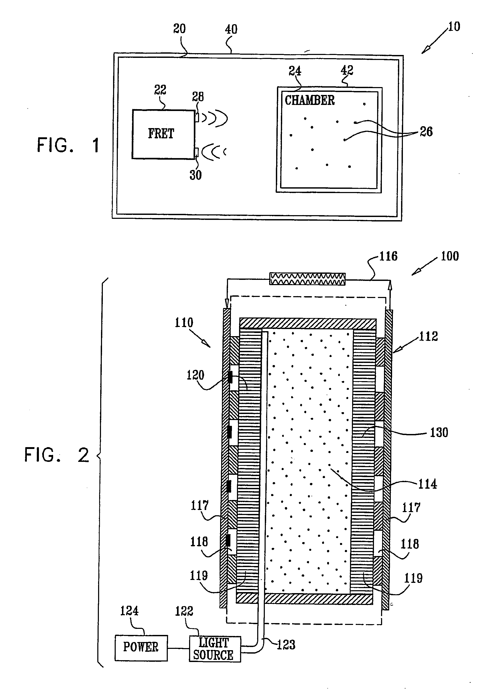
[0150]FIG. 1 is a schematic illustration of an implantable device 10 for detecting a concentration of a substance in a subject, such as a blood constituent or other body fluid constituent of the subject, in accordance with an embodiment of the present invention. Device 10 comprises an implantable housing 20 that holds a fluorescence resonance energy transfer (FRET) measurement device 22 and cells 26. FRET measurement device 22 comprises a light source 28, such as a laser, and a FRET detector 30. Cells 26 are genetically engineered to produce, in situ, a FRET protein having a FRET complex comprising a fluorescent protein donor, a fluorescent protein acceptor, and a binding site for the substance. The FRET complex is configured such that binding of the substance to the binding site changes the configuration of the complex, and thus the distance between the donor and the acceptor. FRET detector 30 detects this change in distance to determine the quantity of the FRET complex in each of ...


PUM

PropertyMeasurementUnit
molecular weightaaaaaaaaaa
distanceaaaaaaaaaa
concentrationaaaaaaaaaa

Abstract

A protein is provided, including a glucose binding site, cyan fluorescent protein (CFP), and yellow fluorescent protein (YFP). The protein is configured such that binding of glucose to the glucose binding site causes a reduction in a distance between the CFP and the YFP. Substance monitoring apparatus (210) is also provided, including a semi-permeable barrier (212), adapted to be implanted in a body of a subject and to allow passage therethrough of a substance, while inhibiting passage therethrough of immune cells; and microorganisms (214), disposed within the semi-permeable barrier (212) so as to produce a measurable response to a level of the substance. A sensor (220) is adapted to measure the measurable response and not to measure a response of any mammalian cells that may be disposed within the semi-permeable barrier (212).

Description

CROSS-REFERENCES TO RELATED APPLICATIONS[0001]The present application claims the benefit of: (i) U.S. Provisional Patent Application 60 / 658,716, filed Mar. 3, 2005, entitled, “Implantable power sources and sensors,” and (ii) U.S. Provisional Patent Application 60 / 588,211, filed Jul. 14, 2004, entitled, “Implantable sensor.” Both of these applications are incorporated herein by reference.FIELD OF THE INVENTION[0002]The present invention relates generally to implantable power sources and sensors, and specifically to implantable bio-fuel cells and methods and apparatus for sensing blood glucose concentrations.BACKGROUND OF THE INVENTION[0003]Fluorescence resonance energy transfer (FRET) is the transfer of photon energy from an excited fluorophore (the donor) to another fluorophore (the acceptor) without the emission of a photon, when the donor and acceptor molecules are in close proximity to each other. FRET enables the determination of the relative proximity of the molecules, for inve...

Claims


Application Information

Patent Timeline
Patent Type & Authority Applications(United States)
IPC IPC(8): A61B5/145G01N33/66C12Q1/37A61M5/00C12Q1/54
CPCA61B5/14532A61K49/0045A61K49/0047A61K49/0056C07K14/43595C07K2319/60G01N33/54373
Inventor GROSSWILLIGER, BEN-TSIONHYMAN, TEHILANEUFELD, TOVA
Owner GLUSENSE LTD
Learn More