Optical measuring apparatus and optical measuring method

Inactive Publication Date: 2009-01-08
YOKOGAWA ELECTRIC CORP
View PDF4 Cites 8 Cited by
  • Summary
  • Abstract
  • Description
  • Claims
  • Application Information

AI Technical Summary

Benefits of technology

[0036]Also, the electric signal involving the cosine (sine) oscillation can be obtained steadily from the optical phase diversity circuit. Therefore, the components whose low frequency characteristic is poor (which does not correspond t

Problems solved by technology

As a result, such a problem exists in the measuring approach in the related art that a range of the measured wavelength is limited depending upon the light source.
Also, an amount of change of the intensity (an amount of

Method used


Image

  • Optical measuring apparatus and optical measuring method
  • Optical measuring apparatus and optical measuring method
  • Optical measuring apparatus and optical measuring method

Examples


embodiment 1

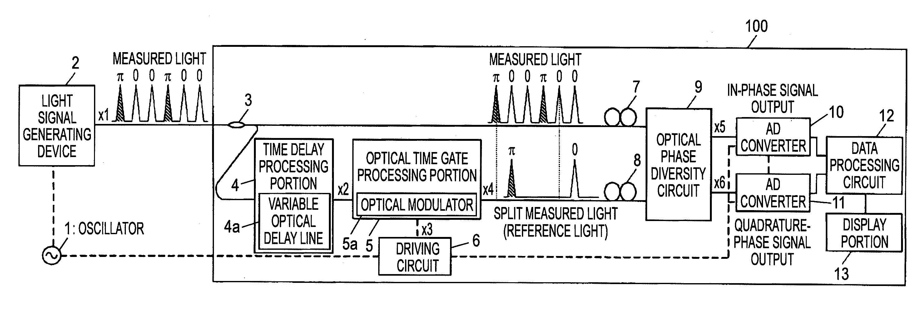
[0068]Embodiment 1 of the present invention will be explained with reference to FIG. 1 to FIG. 16 hereunder.

[0069]An internal configuration of an optical measuring apparatus 100 according to Embodiment 1 and an oscillator 1 and a light signal generating device 2 are shown in FIG. 1.

[0070]The oscillator 1 outputs an electric clock signal, which is in synchronism with the measured light generated by the light signal generating device 2, to the light signal generating device 2 and a driving circuit 6 of the optical measuring apparatus 100.

[0071]On the assumption that data propagating through the actual transmission line should be superposed on the light signal, the light signal generating device 2 generates the measured light on which random data is superposed, in synchronism with the electric clock signal that is input from the oscillator 1. As the measured light on which the random data are superposed, there is the light signal that is modulated by the DPSK system, for example.

[0072]...

embodiment 2

[0127]Embodiment 2 of the present invention will be explained with reference to FIG. 17 and FIG. 18 hereunder.

[0128]In Embodiment 2, the electric time gate processing portion 88 is employed as shown in FIG. 17 in place of the optical time gate processing portion 5 in Embodiment 1.

[0129]An example of an internal configuration of an optical measuring apparatus 500 according to Embodiment 2 of the present invention is shown in FIG. 17. In this case, in Embodiment 2, the same reference symbols are affixed to the same constituent elements as those of the optical measuring apparatus 100 of Embodiment 1. Only different points from the optical measuring apparatus 100 of Embodiment 1 will be explained hereunder.

[0130]As shown in FIG. 17, the optical measuring apparatus 500 is constructed by an optical branch element 86, a time delay processing portion 87, the polarization controllers 7, 8, an optical phase diversity circuit 90, an electric time gate processing portion 88, a driving circuit 8...

embodiment 3

[0152]Embodiment 3 of the present invention will be explained with reference to FIG. 20 to FIG. 26 hereunder.

[0153]In Embodiment 3, the frequency shifter is employed.

[0154]In the approach in Embodiment 2, since the delayed self-homodyne approach is employed, the electric signal (the in-phase signal component and the quadrature-phase signal component) obtained by the optical phase diversity circuit 90 after the photoelectric conversion contains the direct current (DC) component. When the measured light is seldom subject to the modulation and comes closer to the constant signal, such measured light contains a larger amount of low frequency component near the DC. Therefore, in order to execute the precise measurement, the components having the good low-frequency characteristic (to the DC component) are needed in the electric circuits subsequent to the optical phase diversity circuit 90. For example, when the electric signal from the optical phase diversity circuit 90 should be amplifie...


PUM


Abstract

An optical measuring apparatus, includes an optical branch element for splitting a measured light into plural lights, a time delay processing portion for giving a predetermined time delay to one split light of the measured light, an optical phase diversity circuit for outputting an in-phase signal component and an quadrature-phase signal component of the measured light by virtue of an interference between the measured light and a reference light between which a relative time difference corresponds to a time give by the time delay, while using other split light of the measured light or the measured light to which a process is applied by the time delay processing portion as the reference light, a data processing circuit for calculating at least one of an amount of change of an amplitude and an amount of change of a phase of the measured light, based on the in-phase signal component and the quadrature-phase signal component, and an optical time gate processing portion or an electric time gate processing portion provided on a route extending from the optical branch element to the data processing circuit, for extracting at least one of split lights of the measured light every predetermined bit time while shifting a timing, wherein changes of amplitude/phase distributions in time are measured.

Description

[0001]This application claims priority to Japanese Patent Application No. 2007-153649, filed Jun. 11, 2007, in the Japanese Patent Office. The Japanese Patent Application No. 2007-153649 is incorporated by reference in its entirety.TECHNICAL FIELD[0002]The present disclosure relates to an optical measuring apparatus and an optical measuring method for measuring a time change in amplitude / phase distributions of a light signal.RELATED ART[0003]Recent years, as the transmission signal used in the optical communication, the phase modulation system in which information are added to a phase of a light as well as the intensity modulation system in the related art has been proposed. As the digital phase modulation system, there are BPSK (Binary Phase Shift-Keying) in which binary digital values are correlated with 0, π the optical phase, DPSK (Differential Phase Shift-Keying) in which digital values are discriminated based on a phase difference between adjacent bits, and the like, for examp...

Claims


Application Information

Patent Timeline
IPC IPC(8): G01B9/02
CPCG01J9/02H04B10/61H04B10/07
Inventor TANIMURA, KAZUNORI
Owner YOKOGAWA ELECTRIC CORP
Why Eureka
Try Eureka