Method and apparatus for thermochemical recuperation with partial heat recovery of the sensible heat present in products of combustion

a technology of thermochemical recuperation and sensible heat, which is applied in the field of heat and thermal chemical processes, can solve the problems of significant energy waste, need for ready availability of hydrogen, etc., and achieve the effects of increasing the enthalpy of fuel and combustion oxidant, increasing the chemical energy of fuel, and increasing the enthalpy

Inactive Publication Date: 2009-01-08
GAS TECH INST
View PDF4 Cites 34 Cited by
  • Summary
  • Abstract
  • Description
  • Claims
  • Application Information

AI Technical Summary

Benefits of technology

[0011]These and other objects of this invention are addressed by a system for fuel reforming comprising at least one wall enclosing a combustion chamber having a primary fuel inlet, a primary oxidant inlet, and an exhaust gas outlet. Disposed downstream of the combustion chamber is a first stage heat exchange vessel having a first stage exhaust gas inlet in fluid communication with the exhaust gas outlet of the combustion chamber and having a first stage exhaust gas outlet. A reformer fuel conduit having a reformer fuel inlet in fluid communication with a reformer fuel supply and having a reformed fuel outlet in fluid communication with the combustion chamber is disposed within the first stage heat exchange vessel. To enable use of the exhaust gas as a reactant in the reforming process, the first stage exhaust gas outlet is in fluid communication with the reformer fuel inlet. In this manner, the exhaust gas from the combustion chamber is used to increase the enthalpy of the fuel and the combustion oxidant, e.g. air, and to increase the chemical energy of the fuel. The increased enthalpies and chemical energy of the fuel provide higher heat input to the combustion chamber, increase efficiency of the combustion process and decrease the fuel consumption by the combustion process.
[0012]In accordance with the method of this invention, the exhaust gas is used for chemical conversion (reforming) of a fuel (referred to herein as a “reformer fuel”) to a state of higher chemical energy and for combustion air preheat. In order to reform the reformer fuel, it is mixed at a certain ratio with the exhaust gas, after which the mixture is heated in a reformer to reform the fuel. As a result of the reforming process, the reformed fuel that is produced contains hydrogen and carbon monoxide which may be supplied to burners for combustion. The thermal reforming process is accompanied by absorption of a considerable amount of heat (endothermic process), thus recovering much more heat in comparison with conventional thermal-only recuperation that leads to a potential for a substantial increase in furnace productivity and improved product quality, a substantial increase in system thermal efficiency, reduction in specific consumption of fuel, and considerable reduction in pollutant emissions. The amount of the exhaust gas for reforming may be slightly higher, equal to, or less than theoretical values to provide the highest thermal process efficiency. A reformed fuel cooling device may be used to reduce the temperature of the fuel at the combustion chamber fuel inlet and / or partially remove moisture from the fuel.

Problems solved by technology

However, one problem associated with the use of hydrogen in such applications is the requirement for ready availability of the hydrogen in a form suitable for use therein.
Thus, one issue which needs to be addressed is the production of H2 in a manner which satisfies the availability requirements.
In a typical combustion process, a significant amount of energy is wasted.

Method used


Image

  • Method and apparatus for thermochemical recuperation with partial heat recovery of the sensible heat present in products of combustion
  • Method and apparatus for thermochemical recuperation with partial heat recovery of the sensible heat present in products of combustion
  • Method and apparatus for thermochemical recuperation with partial heat recovery of the sensible heat present in products of combustion

Examples


Embodiment Construction

[0020]As used herein, the term “combustion process” refers to the burning of a fuel in a combustion chamber, such as an industrial furnace, and explicitly excludes the combustion of a fuel in internal combustion engines, turbines, and the like.

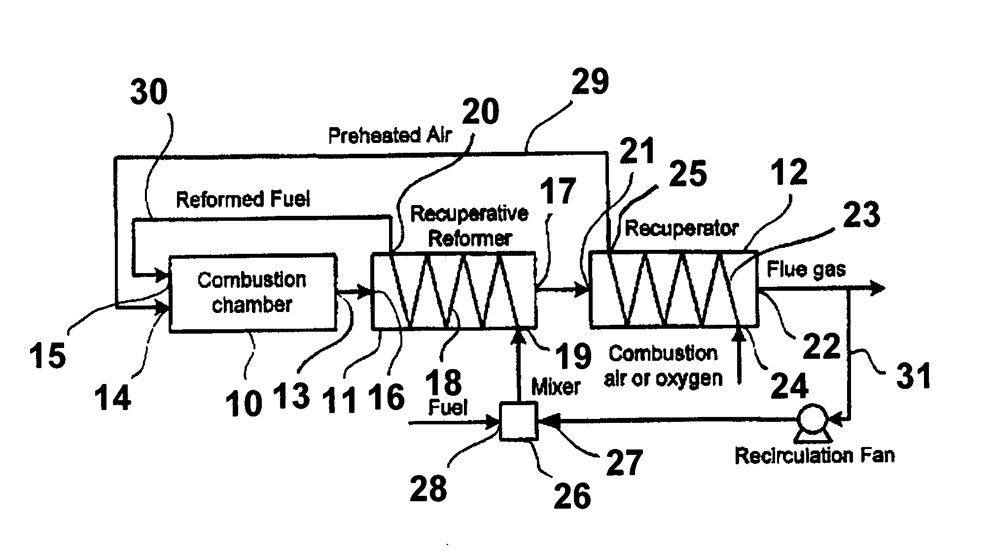
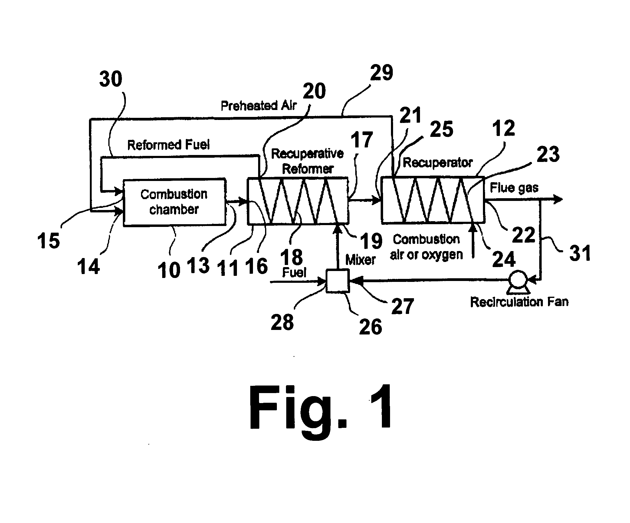
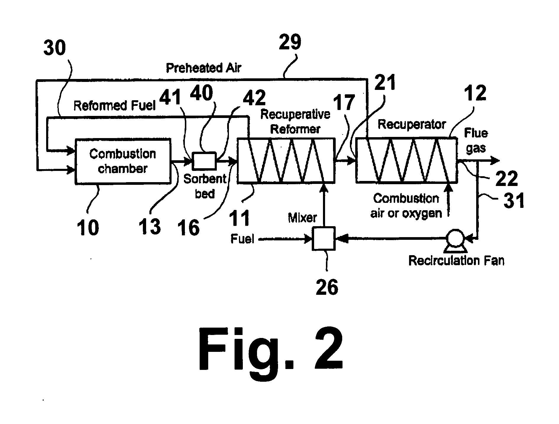
[0021]This invention relates to thermochemical recuperation systems with exhaust (flue) gas / fuel reforming. The recuperative process is characterized by chemical reaction temperatures in the range of about 500° F. to about 1800° F. and can take place at a low absolute pressure (about 14.7 psig or lower) or high pressure (higher than 14.7 psig). Higher temperature is needed to achieve higher reforming rates of the fuel and higher efficiencies. Exhaust gas / fuel ratio depends upon the type of fuel used in the combustion process. For natural gas or methane (CH4), the exhaust gas / methane optimal mole ratio is from about 1:100 to about 1:3 (⅓×{CO2+2H2O+7.52N2}+CH4) depending upon temperature and exhaust gas composition. The stoichiometric, theoretic...


PUM

PropertyMeasurementUnit
pressureaaaaaaaaaa
temperaturesaaaaaaaaaa
temperatureaaaaaaaaaa

Abstract

A system and method for fuel reforming in which at least a portion of the exhaust gases from a combustion process, such as an industrial furnace, is mixed with a fuel, such as natural gas, and the mixture is introduced into a first stage heat exchange vessel in which the fuel is reformed. The reformed fuel is then returned to the combustion process for burning. In accordance with one embodiment, primary combustion oxidant is introduced into a second stage heat exchange vessel in which it is heated by a portion of the exhaust gas exiting the first stage heat exchange vessel. The heated oxidant is then introduced into the combustion process for burning of the fuel(s) therein.

Description

BACKGROUND OF THE INVENTION[0001]1. Field of the Invention[0002]This invention relates to heat and thermal chemical processes, in particular, recuperation systems of gas-fired devices. More particularly, this invention relates to thermochemical recuperators and the use of thermochemical recuperators as fuel reformers for providing reformed fuel to a combustion process.[0003]2. Description of Related Art[0004]Natural gas is the most abundant energy source available after coal. Because it is inexpensive and burns very cleanly relative to other energy sources, particularly with respect to coal, more ways are continually being investigated for using natural gas as a fuel. In addition, because natural gas is in abundant supply, using more natural gas as an energy source provides a means for reducing dependence on imported foreign oils.[0005]Over the past several years, fuel cells, which typically use hydrogen (H2) as a fuel, have been receiving a substantial amount of attention due to th...

Claims


Application Information

Patent Timeline
Patent Type & Authority Applications(United States)
IPC IPC(8): H01M8/18H01M8/04
CPCB01J19/0013Y02E60/50B01J19/2425B01J2219/00006B01J2219/00094B01J2219/00117B01J2219/00772C01B3/34C01B2203/0233C01B2203/0238C01B2203/0822C01B2203/0827C01B2203/0883C01B2203/12C01B2203/1241C01B2203/142C01B2203/148H01M8/0618B01J19/006Y02P20/10Y02P20/141
Inventor CHUDNOVSKY, YAROSLAVKOZLOV, ALEKSANDRRUE, DAVIDKHINKIS, MARK J.NOSACH, VILYAM G.KUREK, HARRY S.
Owner GAS TECH INST
Why Eureka
Try Eureka