
External cathode ion source

a cathode and ion source technology, applied in the field of ion sources, can solve the problems of providing a relatively long life, filaments are known to fail in such harsh environments, and subject to a relatively harsh environmen

Inactive Publication Date: 2009-01-15
SEMEQUIP
View PDF55 Cites 38 Cited by
  • Summary
  • Abstract
  • Description
  • Claims
  • Application Information

AI Technical Summary

Problems solved by technology

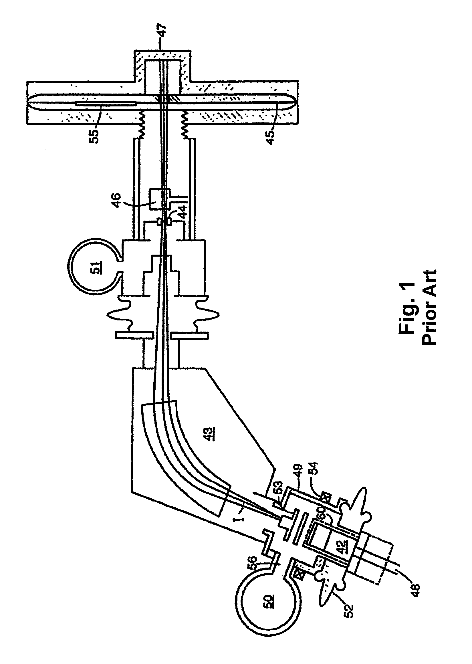
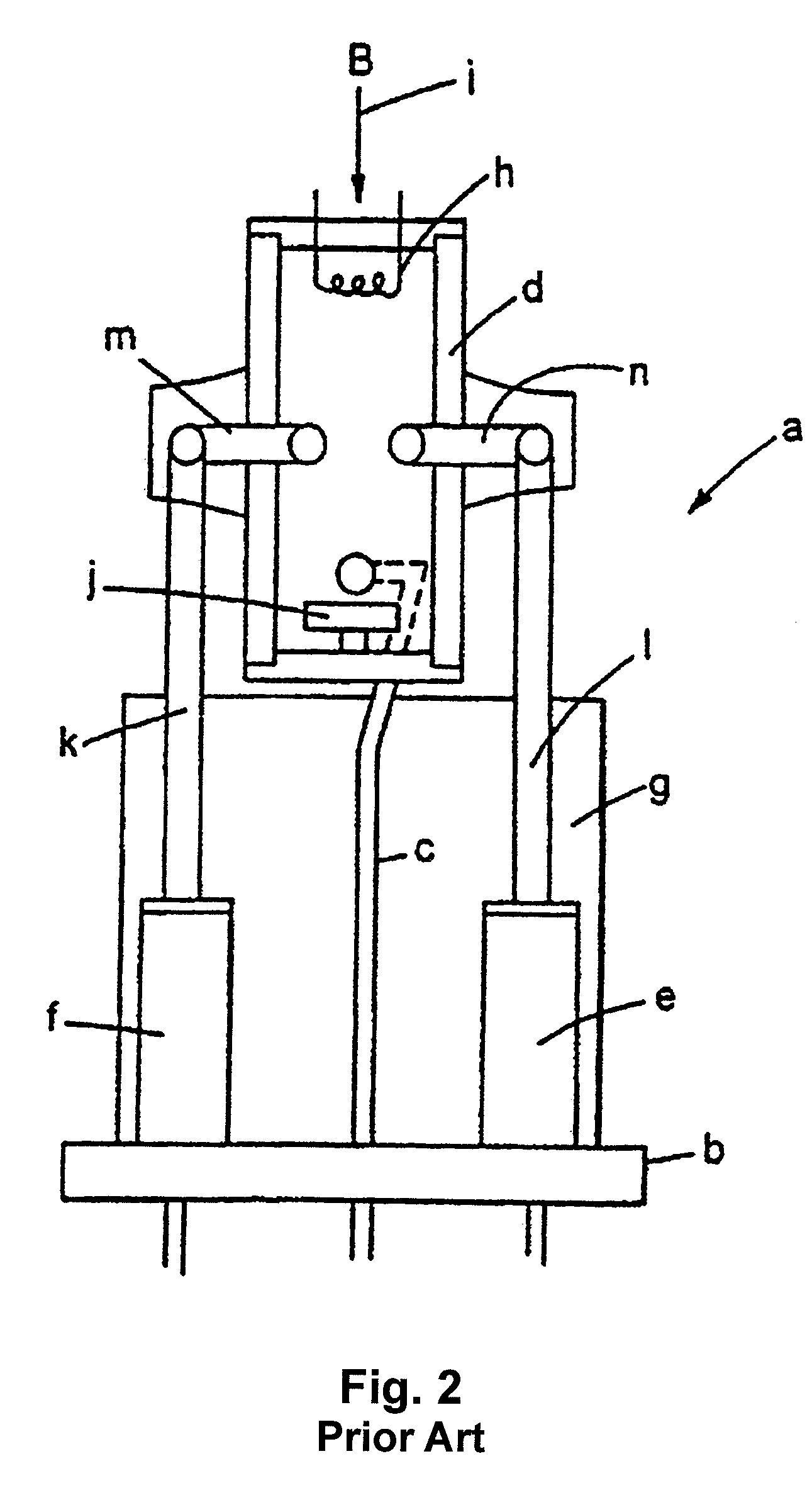
In known ion implantation systems, electron emitters with such heated and indirectly heated cathodes are normally disposed within an ionization chamber and are therefore subject to a relatively harsh environment as a result of the plasma developed within the ionization chamber.
These filaments are known to fail in such harsh environments in a relatively short time.
Although, the IHC is exposed to a harsh plasma environment, the massive cathode having a substantially larger mass than the filament of a directly heated cathode provides a relatively longer life than such directly heated cathodes.
Also the significant material deposits that some of the cluster materials produce favor the removal of the emitter from the source, as there is a risk of building up flakes that will short the IHC to the ionization chamber potential.
Now the emitter is removed from the higher gas pressure of the ionization chamber into the usually pumped source housing, where the gas pressure can be an order of magnitude or more lower, striking an arc discharge between the IHC emitter and the source will become more difficult.
If plasma is ignited, there will be significant diffusion losses before the bulk of the plasma would get into the ionization chamber.
The downside is that the distance the electrons are traveling will increase by the extent of the anode and anode gap.
This can lead into voltage holding issues.
With other feed materials, however, detrimental deposits have formed in hot ion sources.
Cold ion sources suffer more from the deposition of feed materials than do hot sources.
The use of these gases and vapors in cold ion sources has resulted in significant materials deposition and has required the ion source to be removed and cleaned, sometimes frequently.
These ion sources suffer from cross-contamination (between N- and P-type dopants) and also from particle formation due to the presence of deposits.
When transported to the substrate, particles negatively impact yield.
Cross-contamination effects have historically forced FPD manufacturers to use dedicated ion implanters, one for N-type ions, and one for P-type ions, which has severely affected cost of ownership.
Boron hydrides such as decaborane and octadecaborane present a severe deposition problem when used to produce ion beams, due to their propensity for readily dissociating within the ion source.
Eventually, depending on the design of the ion source, the buildup of condensed material interferes with the operation of the source and necessitates removal and cleaning of the ion source.
Contamination of the extraction electrode has also been a problem when using these materials.
Such instabilities affect the precision quality of the ion beam and can contribute to the creation of contaminating particles.
While such dual mode ion sources are a significant improvement over single mode ion sources, the need for multiple electron emitters in a single ion source adds a substantial amount of complexity.

Method used


Image

  • External cathode ion source
  • External cathode ion source
  • External cathode ion source

Examples


Embodiment Construction

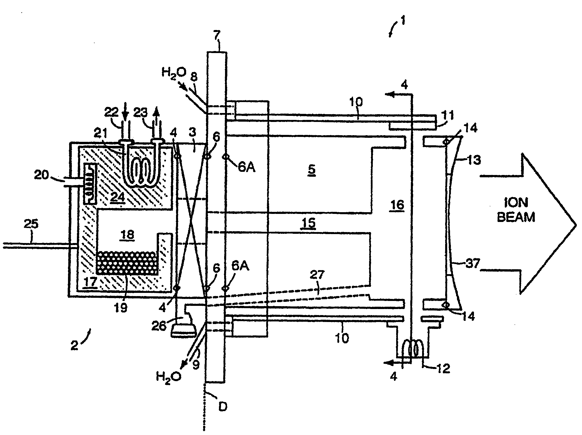
[0060]The present invention relates to an ion source which includes a single electron emitter that is configured with a cathode mounted external to the ionization chamber for use in fabrication of semiconductors. The ionization chamber is formed with an electron entrance aperture in one wall thereof. In accordance with one aspect of the invention, the cathode portion of the electron emitter, which may be either directly heated or indirectly heated, is located external to the ionization chamber. The cathode is juxtaposed so that emitted electrons are received by the electron entrance aperture and directed into the ionization chamber in order to ionize feed gases or vapors within the ionization chamber. In accordance with an important aspect of the present invention, the anode or other electron optics normally associated with the electron emitter are eliminated to enable the distance, i.e. gap, between the electron emitter and the ionization to be shortened. By shortening this distanc...


PUM


Abstract

An ion source is disclosed for use in fabrication of semiconductors. The ion source includes an electron emitter that includes a cathode mounted external to the ionization chamber for use in fabrication of semiconductors. In accordance with an important aspect of the invention, the electron emitter is employed without a corresponding anode or electron optics. As such, the distance between the cathode and the ionization chamber can be shortened to enable the ion source to be operated in an arc discharge mode or generate a plasma. Alternatively, the ion source can be operated in a dual mode with a single electron emitter by selectively varying the distance between the cathode and the ionization chamber.

Description

CROSS-REFERENCE TO RELATED APPLICATIONS[0001]This application is a continuation-in-part of U.S. patent application Ser. No. 11 / 648,506, filed Dec. 29, 2006, which is a continuation of U.S. patent application Ser. No. 10 / 887,426, filed on Jul. 8, 2004, now U.S. Pat. No. 7,185,602, which is a divisional of U.S. patent application Ser. No. 10 / 170,512, filed Jun. 12, 2002, now U.S. Pat. No. 7,107,929, which is a continuation of International Patent Application No. PCT / US00 / 33786, filed Dec. 13, 2000, which claims priority of and benefit of U.S. Provisional Patent Application No. 60 / 170,473 filed on Dec. 13, 1999, U.S. Provisional Patent Application No. 60 / 250,080 filed on Nov. 3, 2000.BACKGROUND OF THE INVENTION[0002]1. Field of Invention[0003]The present invention relates to an ion source for use in semiconductor fabrication and more particularly to an ion source configured with its cathode located external to the ionization chamber, the ion source being operable in a first mode of ope...

Claims


Application Information

Patent Timeline
IPC IPC(8): G21K5/10
CPCH01J27/205H01J37/08H01J2237/31701H01J2237/082H01J2237/0835H01J2237/024
Inventor HAHTO, SAMI K.GOLDBERG, RICHARDMCINTYRE, EDWARDHORSKY, THOMAS N.
Owner SEMEQUIP
Learn More