Segmented thermal barrier coating

a thermal barrier and segmented technology, applied in the direction of superimposed coating process, machine/engine, natural mineral layered products, etc., can solve the problems of coating spalling, coating spalling, and superalloy materials not being able to survive long-term operation at temperatures sometimes exceeding 1,400 degrees

Inactive Publication Date: 2009-01-15
SIEMENS ENERGY INC
View PDF6 Cites 159 Cited by
  • Summary
  • Abstract
  • Description
  • Claims
  • Application Information

AI Technical Summary

Problems solved by technology

Although nickel and cobalt based superalloy materials are now used for components in the hot gas flow path, such as combustor transition pieces and turbine rotating and stationary blades, even these superalloy materials are not capable of surviving long term operation at temperatures sometimes exceeding 1,400 degrees C. In many applications a metal substrate is coated with a ceramic insulating material in order to reduce the service temperature of the underlying metal and to reduce the magnitude of the temperature transients to which the metal is exposed.
Such differential thermal expansion creates stresses within the coating that can result in the spalling of the coating along one or more planes parallel to the substrate surface.
This difference in densification also creates stresses within the coating that may result in spalling of the coating.
However, it is extremely difficult to form a desirable columnar grain structure with the APS process.
Accordingly, for applications where the operating temperature will extend damaging temperature transients into the coating to a depth greater than a few mils, this technique offers little benefit.
Such special deposition parameters may place undesirable limitations upon the fabrication process for a partic

Method used


Image

  • Segmented thermal barrier coating
  • Segmented thermal barrier coating
  • Segmented thermal barrier coating

Examples


Embodiment Construction

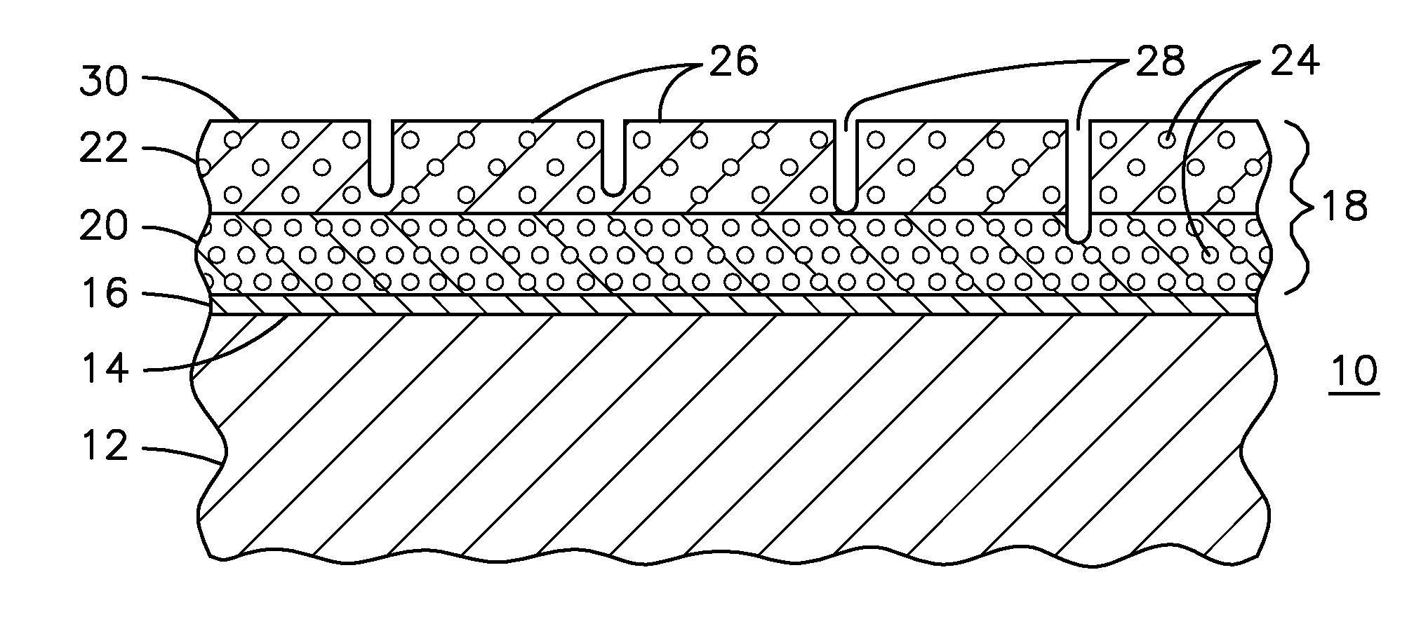
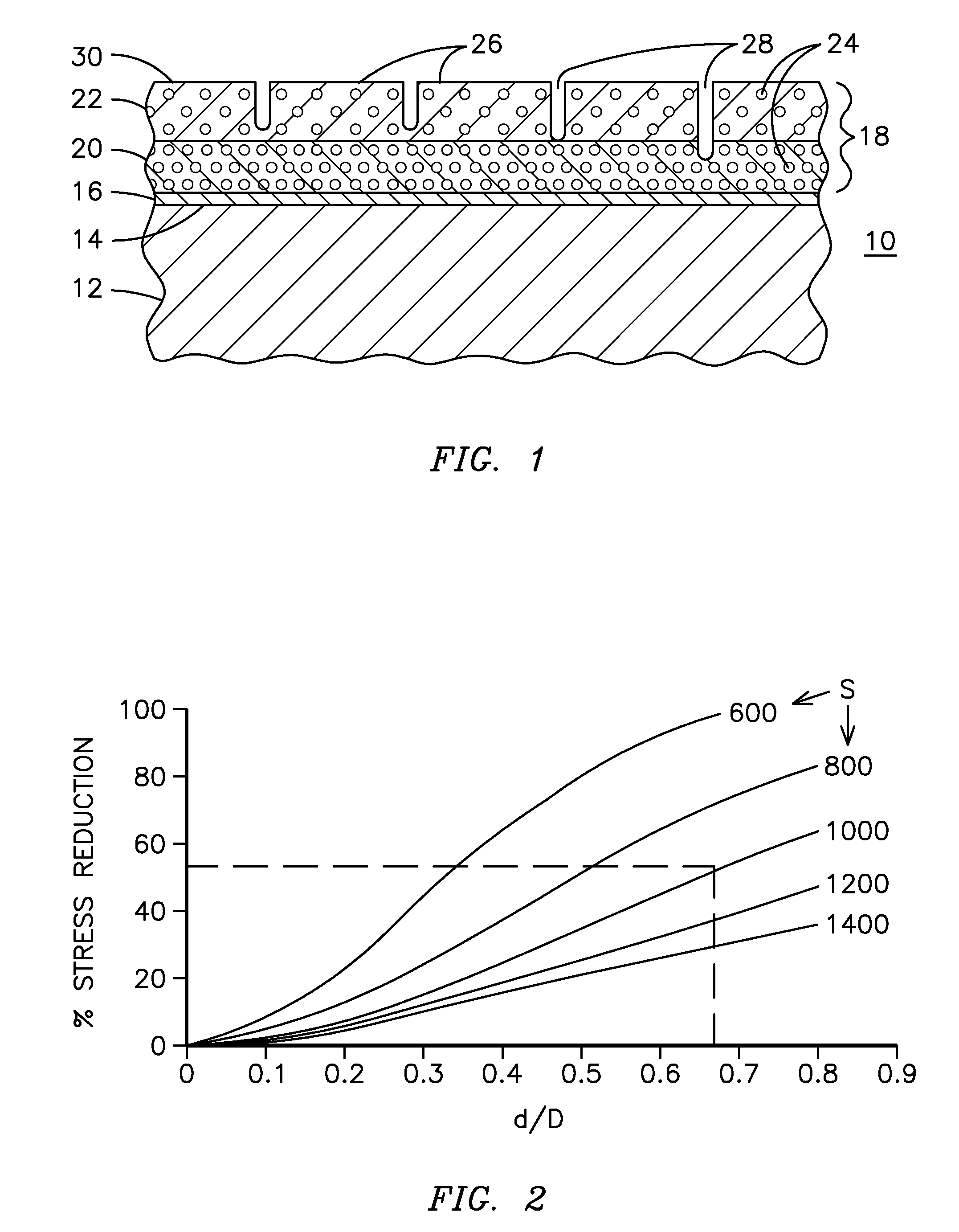
[0026]FIG. 1 illustrates a partial cross-sectional view of a component 10 formed to be used in a very high temperature environment. Component 10 may be, for example, the airfoil section of a combustion turbine blade or vane. Component 10 includes a substrate 12 having a top surface 14 that will be exposed to the high temperature environment. For the embodiment of a combustion turbine blade, the substrate 12 may be a superalloy material such as a nickel or cobalt base superalloy, and is typically fabricated by casting and machining. In other embodiments the substrate may be a ceramic matrix composite material or any known structural material. The substrate surface 14 is typically cleaned to remove contamination, such as by aluminum oxide grit blasting, prior to the application of any additional layers of material. A bond coat 16 may be applied to the substrate surface 14 in order to improve the adhesion of a subsequently applied thermal barrier coating and to reduce the oxidation of ...


PUM

PropertyMeasurementUnit
Fractionaaaaaaaaaa
Fractionaaaaaaaaaa
Fractionaaaaaaaaaa

Abstract

A ceramic thermal barrier coating (TBC) (18) having first and second layers (20, 22), the second layer (22) having a lower thermal conductivity than the first layer for a given density. The second layer may be formed of a material with anisotropic crystal lattice structure. Voids (24) in at least the first layer (20) make the first layer less dense than the second layer. Grooves (28) are formed in the TBC (18) for thermal strain relief. The grooves may align with fluid streamlines over the TBC. Multiple layers (84, 86,88) may have respective sets of grooves (90), Preferred failure planes parallel to the coating surface (30) may be formed at different depths (A1, A2, A3) in the thickness of the TBC to stimulate generation of a fresh surface when a portion of the coating fails by spalling. A dense top layer (92) may provide environmental and erosion resistance.

Description

CROSS-REFERENCE TO RELATED APPLICATIONS[0001]This application is a continuation-in-part of U.S. patent application Ser. No. 10 / 649,536 filed Aug. 26, 2003, which is a continuation-in-part of U.S. patent application Ser. No. 09 / 921,206 filed Aug. 2, 2001, now patent U.S. Pat. No. 6,703,137 issued Mar. 9, 2004. This application is also a continuation-in-part of U.S. patent application Ser. No. 12 / 101,460 filed Apr. 11, 2008. These parent applications are incorporated herein by reference.FIELD OF THE INVENTION[0002]This invention relates generally to thermal barrier coatings and in particular to a strain tolerant thermal barrier coating for a gas turbine component and a method of manufacturing the same.BACKGROUND OF THE INVENTION[0003]It is known that the efficiency of a combustion turbine engine will improve as the firing temperature of the combustion gas is increased. As the firing temperatures increase, the high temperature durability of the components of the turbine must increase c...

Claims


Application Information

Patent Timeline
IPC IPC(8): B32B18/00
CPCC23C4/18C23C30/00F01D5/288F01D11/122C23C28/042C23C28/048Y10T428/24521C23C28/345C23C28/3455C23C28/36F05D2230/13F05D2300/21C23C28/3215Y10T428/249953Y10T428/249967Y10T428/24997Y10T428/249981
Inventor KULKARNI, ANAND A.MITCHELL, DAVID J.SUBRAMANIAN, RAMESHBURNS, ANDREW J.
Owner SIEMENS ENERGY INC
Why Eureka
Try Eureka