R-t-b system sintered magnet
a sintered magnet and r-t-b technology, applied in the field of rtb, can solve the problems of difficult to achieve both a high residual magnetic flux density and a high coercive force, and achieve the effect of high residual magnetic flux density and high coercive for
- Summary
- Abstract
- Description
- Claims
- Application Information
AI Technical Summary
Benefits of technology
Problems solved by technology
Method used
Image
Examples
example 1
[0067]The two raw material alloys (first alloy and second alloy) shown in the row a in Table 1 were prepared in an Ar atmosphere by high frequency dissolution.
[0068]The first alloy and the second alloy thus prepared were mixed together in a weight ratio of 50:50; thereafter, the mixture thus obtained was made to absorb hydrogen at room temperature, and then subjected to a dehydrogenation treatment in an Ar atmosphere at 600° C. for one hour. Then, the mixture was crushed in a nitrogen atmosphere with a Brown mill.
[0069]The crushed powders thus obtained were added with zinc stearate as a crushing agent in a content of 0.05%. Then, the crushed powders were pulverized with a jet mill by using high-pressure nitrogen gas to obtain pulverized powders having a mean particle size of 4.5 μm.
[0070]The fine powders thus obtained were compacted to obtain a compacted body in a magnetic field of 15 kOe (1200 kA / m) under a pressure of 1.5 ton / cm2 (150 MPa). The compacted body thus obtained was sin...
example 2
[0076]Sintered magnets were prepared by the same process as in Example 1 except that the four types of raw material alloys (first alloy and second alloy) a to d having the compositions shown in Table 1 were prepared and the sintering conditions were set such that 1020° C.×6 hours.
[0077]Each of the sintered bodies thus obtained was subjected to the measurements of the residual magnetic flux density (Br) and the coercive force (HcJ). The result of a composition analysis of each of the sintered magnets was found to be 20% Nd-5% Pr-5% Dy-2% Co-0.1% Cu-1% B-bal.Fe.
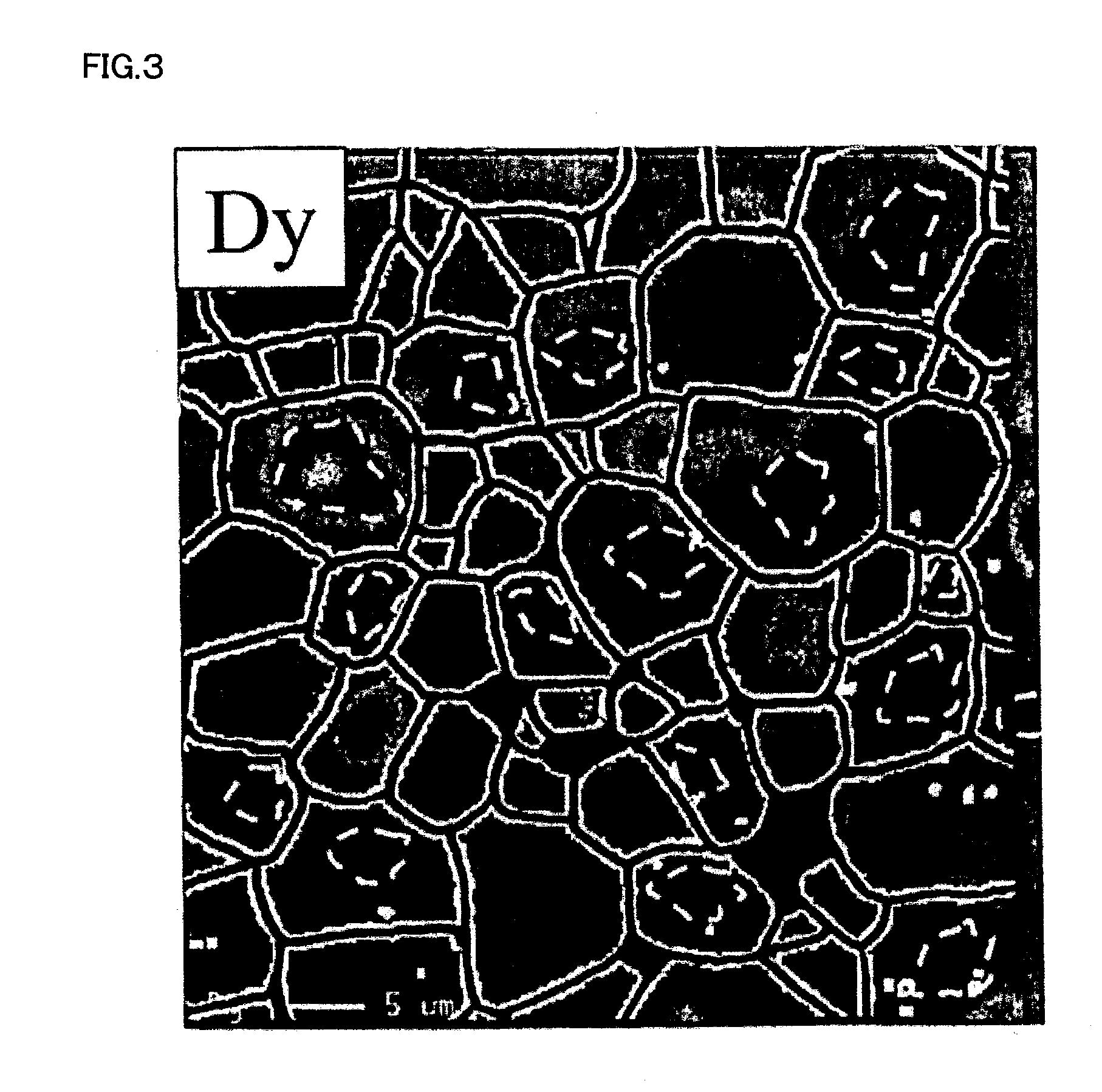
[0078]Additionally, the main phase grains of each of the sintered bodies thus obtained were subjected, in the same manner as in Example 1, to the element mapping analysis by means of EPMA and to the element mapping analysis and the quantitative analysis by means of EDS using a transmission electron microscope. Further, on the basis of the results of the EPMA mapping analysis, the number of the main phase grains and the number o...
example 3
[0083]Sintered magnets were prepared by the same process as in Example 1 except that the three types of raw material alloys (first alloy and second alloy) e to g shown in Table 4 were prepared, the first alloy and the second alloy in each of the raw material alloys were mixed together in the weight ratio shown in Table 4, and thereafter the sintering conditions were set such that 1050° C.×4 hours. The result of a composition analysis of each of the sintered magnets thus obtained was found to be 30% Nd-2% Dy-2% Co-0.4% Cu-0.2% Al-0.19% Zr-1% B-bal.Fe.
[0084]The obtained sintered bodies were subjected to the same measurements as in Example 2 and a measurement of the squareness ratio (Hk / HcJ). The results thus obtained are shown in Table 5. Additionally, FIG. 7 shows the concentration distributions (Dy / TRE) of Dy (the heavy rare earth element) in relation to the total amount (TRE) of the rare earth elements. Here, Hk represents the external magnetic field intensity at which the magnetic...
PUM
| Property | Measurement | Unit |
|---|---|---|
| Fraction | aaaaa | aaaaa |
| Fraction | aaaaa | aaaaa |
| Fraction | aaaaa | aaaaa |
Abstract
Description
Claims
Application Information
 - R&D
- Intellectual Property
- Life Sciences
- Materials
- Tech Scout
- Unparalleled Data Quality
- Higher Quality Content
- 60% Fewer Hallucinations
Browse by: Latest US Patents, China's latest patents, Technical Efficacy Thesaurus, Application Domain, Technology Topic, Popular Technical Reports.
© 2025 PatSnap. All rights reserved.Legal|Privacy policy|Modern Slavery Act Transparency Statement|Sitemap|About US| Contact US: help@patsnap.com


