
Material for organic electroluminescent element and organic electroluminescent element employing the same

a technology of electroluminescent elements and materials, applied in the direction of discharge tube/lamp details, discharge tube luminescnet screens, organic chemistry, etc., can solve the problems of small energy level of excited triplet states of proposed compounds, adversely affecting emitting efficiency and lifetime, and no device performance advantage. , to achieve the effect of high efficiency and high heat resistan

Active Publication Date: 2009-01-29
IDEMITSU KOSAN CO LTD
View PDF2 Cites 1287 Cited by
  • Summary
  • Abstract
  • Description
  • Claims
  • Application Information

AI Technical Summary

Benefits of technology

[0012]The present invention has been made to overcome the above problems and has an object of providing a material for organic EL devices which realizes an EL device exhibiting a high efficiency of light emission, causing little pixel defects, exhibiting a high heat resistance and having a long lifetime.
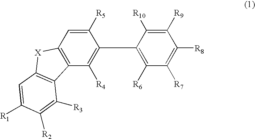
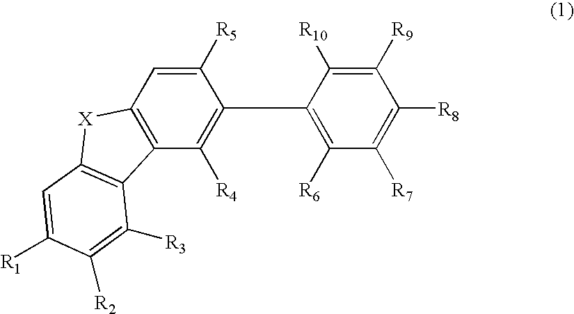
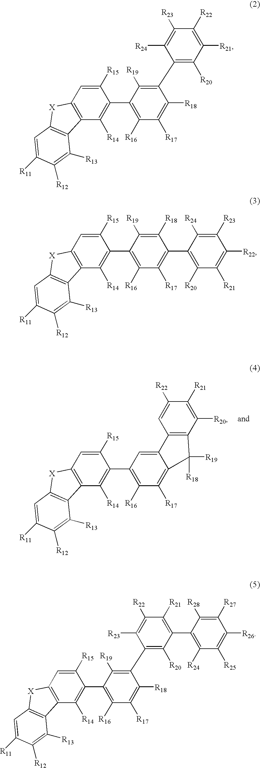
[0013]As a result of extensive reasech in view of achieving the above object, the inventors have found that a compound represented by the following formula 1, which has a dibenzothiophene or dibenzofuran structure having at its 2-position substituted with an aromatic hydrocarbon group, creates a excited triplet state having a sufficient energy level enough to prevent the emitting efficiency of a blue phosphorescent complex from being reduced. It has been further found that the compound realizes a highly efficient and highly heat-resistant organic EL device causing little pixel defects and having a long lifetime. The present invention is based on these findings.
[0016]The organic EL device made using the material for organic EL devices of the present invention is free from pixel defects, highly efficient, highly heat resistant and durable for a long period of time.

Problems solved by technology

However, there is nothing about their advantage in the device performace as compared with a host material having a carbazole structure.
However, the energy level of the excited triplet state of the proposed compounds is small because of the anthracene structure.
If the host material of a phosphorescent device has in its molecule a polymerizable group such as propenylene group, vinylene group and 4-propyl-2-pentenylene group which is formed by introducing an unsaturated bond such as double bond and triple bond, radicals are propagatedly generated in the device to adversely affect the emitting efficiency and lifetime.

Method used


Image

  • Material for organic electroluminescent element and organic electroluminescent element employing the same
  • Material for organic electroluminescent element and organic electroluminescent element employing the same
  • Material for organic electroluminescent element and organic electroluminescent element employing the same

Examples


synthesis example 1

Synthesis of Compound No. 6

[0118]

[0119]A three-necked flask was charged with 3.4 g (1.2 eq., 12 mmol) of compound 1, 3.2 g (1 eq., 10 mmol) of compound 2, 10 ml of 2M Na2CO3 aqueos solution (20 mmol), 50 ml of DME, and 0.58 g of 5 mol % Pd[PPh3]4 (0.5 mmol). The contents were refluxed for 8 hrs in an argon atmosphere.

[0120]After the reaction, the reaction product mixture was cooled to room temperature and poured into a separatory funnel. After adding 50 ml of water, the reaction product mixture was extracted with CH2Cl2. The extract was dried over MgSO4, filtrated and condensed. The condensate was dissolved in 300 ml toluene and purified by a column chromatography. The purified product was condensed, evaporated to dryness and washed with ethyl acetate (30 ml) three times, to obtain a white powder (No. 6) which was then purified by sublimation to obtain 3.5 g of white solid.

FD Mass Spectroscopy Analysis

[0121]C36H23NO: calculated 485, found 485

synthesis example 2

Synthesis of Compound No. 1

[0122]

[0123]A three-necked flask was charged with 7.1 g (1 eq., 15 mmol) of compound 3, 3.8 g (1.2 eq., 18 mmol) of compound 4, 15 ml of 2M Na2CO3 aqueous solution (30 mmol), 50 ml of THF, and 0.87 g of 5 mol % Pd[PPh3]4 (0.75 mmol). The contents were refluxed for 8 hrs in an argon atmosphere.

[0124]After the reaction, the reaction product mixture was cooled to room temperature and poured into 100 ml of methanol. The precipitated solid was filtrated with suction and purified by a column chromatography. The purified product was condensed, evaporated to dryness and recrystallized twice, to obtain a white powder (No. 1) which was then purified by sublimation to obtain 2.6 g of white solid.

[0125]FD Mass Spectroscopy Analysis

[0126]C42H27NO: calculated 561, found 561

synthesis example 3

Synthesis of Compound No. 12

[0127]

[0128]A three-necked flask was charged with 3.4 g (1.2 eq., 16 mmol) of compound 4, 6.5 g (1 eq., 13 mmol) of compound 5, 13 ml of 2M Na2CO3 aqueous solution (26 mmol), 40 ml of DME, and 0.75 g of 5 mol % Pd[PPh3]4 (0.65 mmol). The contents were refluxed for 8 hrs in an argon atmosphere.

[0129]After the reaction, the reaction product mixture was cooled to room temperature and poured into a separatory funnel. After adding 50 ml of water, the reaction product mixture was extracted with CH2Cl2. The extract was purified by a column chromatography. The purified product was condensed, evaporated to dryness and recrystallized twice, to obtain a white powder (No. 12) which was then purified by sublimation to obtain 3.2 g of white solid.

[0130]FD Mass Spectroscopy Analysis

[0131]C42H25NO2: calculated 575, found 575


PUM

PropertyMeasurementUnit
maximum peak wavelengthaaaaaaaaaa
carbon numberaaaaaaaaaa

Abstract

A material for organic electroluminescence devices for use as a host material in combination with at least one phosphorescent metal complex, which comprises a compound having a specific heterocyclic structure, is described. Also described is an organic electroluminescence device having an anode, a cathode and an organic thin film layer having one or more layers. The organic thin film layer is interposed between the anode and cathode and has a light emitting layer containing a host material in combination with at least one phosphorescent metal complex. At least one layer of the organic thin film layer contains the material for organic electroluminescence devices. The material for organic electroluminescence devices provides an organic electroluminescence device which has a high emitting efficiency, causes little pixel defects, is excellent in heat resistance, and show a long lifetime.

Description

BACKGROUND OF THE INVENTION[0001]1. Field of the Invention[0002]The present invention relates to materials for organic electroluminescence devices and organic electroluminescence devices using the materials and, more particularly to materials for organic electroluminescence devices which realize electroluminescence devices exhibiting a high emitting efficiency, causing little pixel defects, exhibiting a high heat resistance and having a long lifetime.[0003]2. Description of the Prior Art[0004]An organic electroluminescence device (organic ELdevice) is a spontaneous emission device which utilizes the phenomenon of fluorescence which occurs by the energy of recombination between holes injected from an anode and electrons injected from a cathode by application of electric field. C. W. Tang of Eastman Kodak Company (C. W. Tang and S. A. Vanslyke, Applied Physics Letters, 51, p. 913, 1987) reported a laminated organic EL device which is driven under low electric voltage. Since that time,...

Claims


Application Information

Patent Timeline
Patent Type & Authority Applications(United States)
IPC IPC(8): C07D487/14C07D405/02C07D405/14C07D407/02C07D407/14H01L51/54C07D409/14C07D409/02C07D471/14C07D471/04
CPCC07D333/76C07D405/10H01L51/5016C07D519/00C07D405/14H10K50/11H10K2101/10
Inventor IWAKUMA, TOSHIHIROENDO, JUNNUMATA, MASAKIFUKUOKA, KENICHI
Owner IDEMITSU KOSAN CO LTD
Learn More