Percutaneously implantable replacement heart valve device and method of making same

a technology of heart valve and implantable device, which is applied in the field of making percutaneous implantable replacement heart valve device, can solve the problems of sudden loss of blood supply to immediate malfunction of the affected body organ, and failure of the valve, and achieves the effects of reducing the risk of heart valve failure, and improving the quality of li

Inactive Publication Date: 2009-01-29
COLIBRI HEART VALVE
View PDF99 Cites 32 Cited by
  • Summary
  • Abstract
  • Description
  • Claims
  • Application Information

AI Technical Summary

Benefits of technology

[0025]The present invention is a replacement heart valve device and method of making same. The replacement heart valve device, in a preferred embodiment, comprises a stent made of stainless steel or self-expanding nitinol and a completely newly designed artificial biological tissue valve disposed within the inner space of the stent. The cusp or leaflet portion of the valve means is formed by folding of the pericardium material preferably used to create the valve without cutting of slits to form leaflets or suturing or otherwise affixing of separate leaflet portions. Other forms of tissue and suitable synthetic materials can also be used for the valve, formed in a sheet of starting material. The folded design provides a number of advantages over prior designs, including improved resistance to tearing at suture lines. The cusps / leaflets open in response to blood flow in one direction and close in response to blood flow in the opposite direction. Preferably the tubular portion of the valve means contains the same number of cusps as the native valve being replaced, in substantially the same size and configuration. The outer surface of the valve means is attached to the stent member.
[0027]The present invention also comprises a method of making a replacement heart valve device. In order to make the valve, the pericardium starting material is isolated and all the fat tissue and extra fibers are removed. The biological membrane material is cleaned by mechanical separation of unwanted layers using hydromechanical force means. Once the pericardium is completely clean, the material is dried in order to make it easier to handle and fold. Preferably, this drying is done by exposing the biocompatible membrane material to photo-mechanical compression to remove all lipids from the pericardium or other biocompatible membrane material and to cause protein denaturalization, transforming the material into a stronger and more homogeneous surface. The valve is formed by taking a flat sheet of the material and folding in such a way that forms a three-leaflet or other number of leaflet valve. Then it is placed in a sequence of solutions, one of isopropyl alcohol of about 70-100%, one of ethanol of about 70-100%, one of glycerol and one of gluteraldehyde, preferably at a concentration of about 0.07-25% for approximately 36 hours. The material is dried in order to make it easier to handle and fold. Preferably this drying is done by exposing the biocompatible membrane material to light and then mechanically compressing the material to cause protein denaturation. This results in material that is stronger and more homogeneous. The valve is formed by taking a flat sheet of bovine pericardium and folding it in such a way that forms a three-leaflet valve. The valve can also be made in the same manner from fresh, cryopreserved or glutaraldehyde fixed allografts or xenografts or synthetic non-biological, non-thrombogenic material. The folding of the pericardium material to create the cusps or leaflets reduces the extent of suturing otherwise required, and resembles the natural form and function of the valve leaflets. The cleaning, pressing and drying technique used to create the valve material makes the folding more practicable. The valve is rehydrated after being formed. The method of the present invention also greatly reduces the risk of tearing of the cusps or leaflets, since they are formed by folding a single uncut portion of material forming the valve rather than being attached by suturing.
[0028]Once the endovascular implantation of the prosthetic valve device is completed in the host, the function of the prosthetic valve device can be monitored by the same methods as used to monitor valve replacements done by open heart surgery. Routine physical examination, periodic echocardiography or angiography can be performed. In contrast to open heart surgery, however, the host requires a short recovery period and can return home within one day of the endovascular procedure. The replacement heart valve device of the present invention can be used in any patient where bioprosthetic valves are indicated, namely elderly patients with cardiac valve diseases, and patients unable to tolerate open heart procedures or life-long anticoagulation medication and treatment. The present invention can be practiced in applications with respect to each of the heart's valves.

Problems solved by technology

Problems that can develop with heart valves consist of stenosis, in which a valve does not open properly, and / or insufficiency, also called regurgitation, in which a valve does not close properly.
In addition to stenosis and insufficiency of heart valves, heart valves may need to be surgically repaired or replaced due to certain types of bacterial or fungal infections in which the valve may continue to function normally, but nevertheless harbors an overgrowth of bacteria (vegetation) on the leaflets of the valve that may embolize and lodge downstream in a vital artery.
If such vegetations are on the valves of the left side (i.e., the systemic circulation side) of the heart, embolization may occur, resulting in sudden loss of the blood supply to the affected body organ and immediate malfunction of that organ.
Likewise, bacterial or fungal vegetations on the tricuspid valve may embolize to the lungs resulting in a lung abscess and therefore, may require replacement of the tricuspid valve even though no tricuspid valve stenosis or insufficiency is present.
These problems are treated by surgical repair of valves, although often the valves are too diseased to repair and must be replaced.
Mechanical valves are typically constructed from nonbiological materials such as plastics, metals and other artificial materials which, while durable, are expensive and prone to blood clotting which increases the risk of an embolism.
Anticoagulants taken to help against blood clotting can further complicate the patient's health due to increased risks for hemorrhages.
The pericardium is a thin and very slippery, which makes it difficult for suturing in a millimetricly precise way.
The major disadvantage of tissue valves is that they lack the long-term durability of mechanical valves.
Tissue valves have a significant failure rate, usually within ten years following implantation.
One cause of these failures is believed to be the chemical treatment of the animal tissue that prevents it from being antigenic to the patient.
In addition, the presence of extensive suturing prevents the artificial tissue valve from being anatomically accurate in comparison to a normal heart valve, even in the aortic valve position.
A shortcoming of prior artificial tissue valves has been the inability to effectively simulate the exact anatomy of a native heart valve.
Additionally, the leaflets of most such tissue valves are constructed by cutting or suturing the tissue material, resulting in leaflets that do not duplicate the form and function of a real valve and are more susceptible to failure.

Method used


Image

  • Percutaneously implantable replacement heart valve device and method of making same
  • Percutaneously implantable replacement heart valve device and method of making same
  • Percutaneously implantable replacement heart valve device and method of making same

Examples


Embodiment Construction

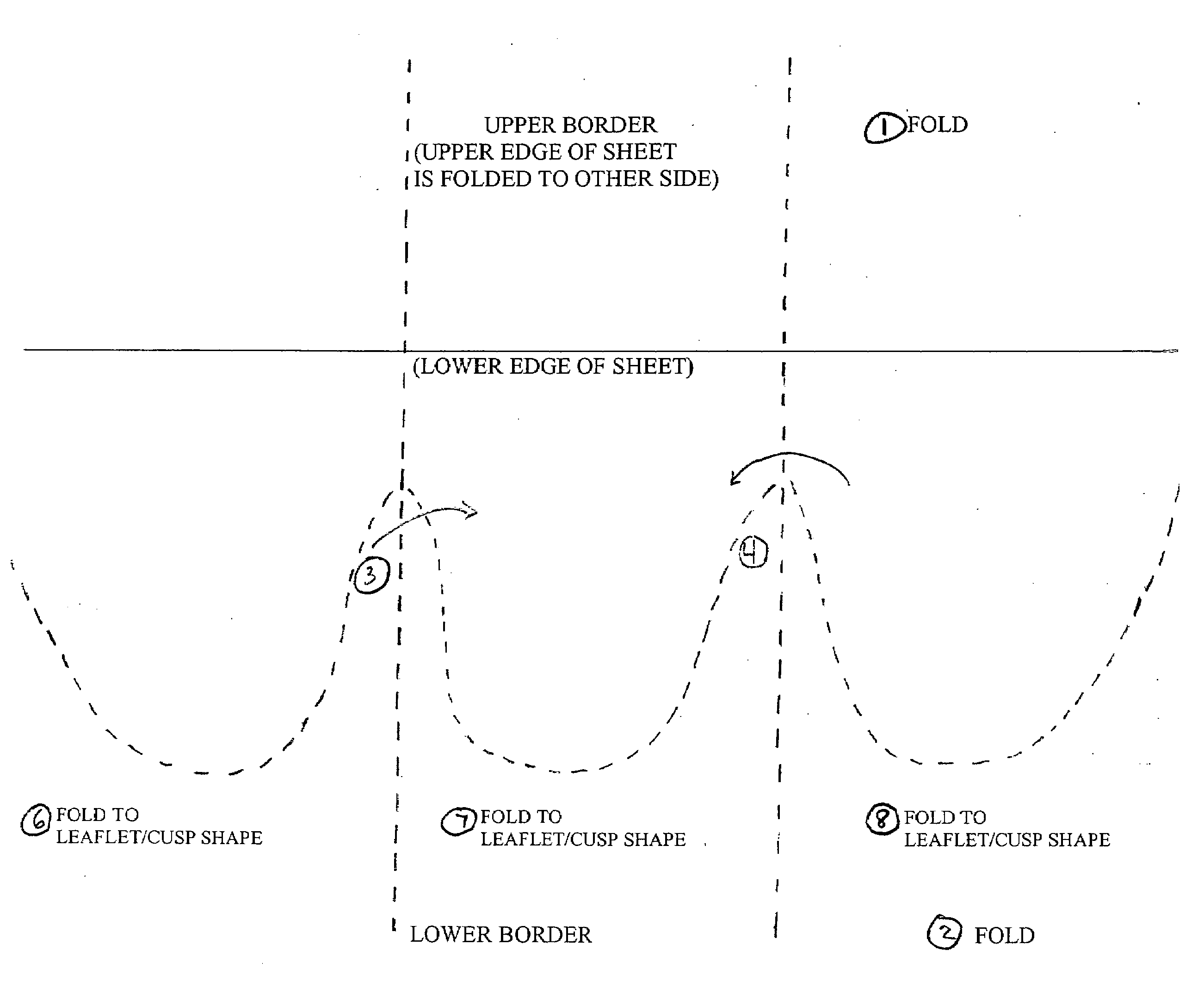
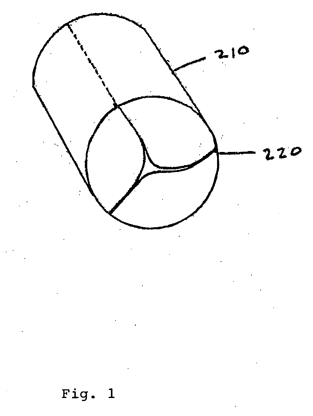
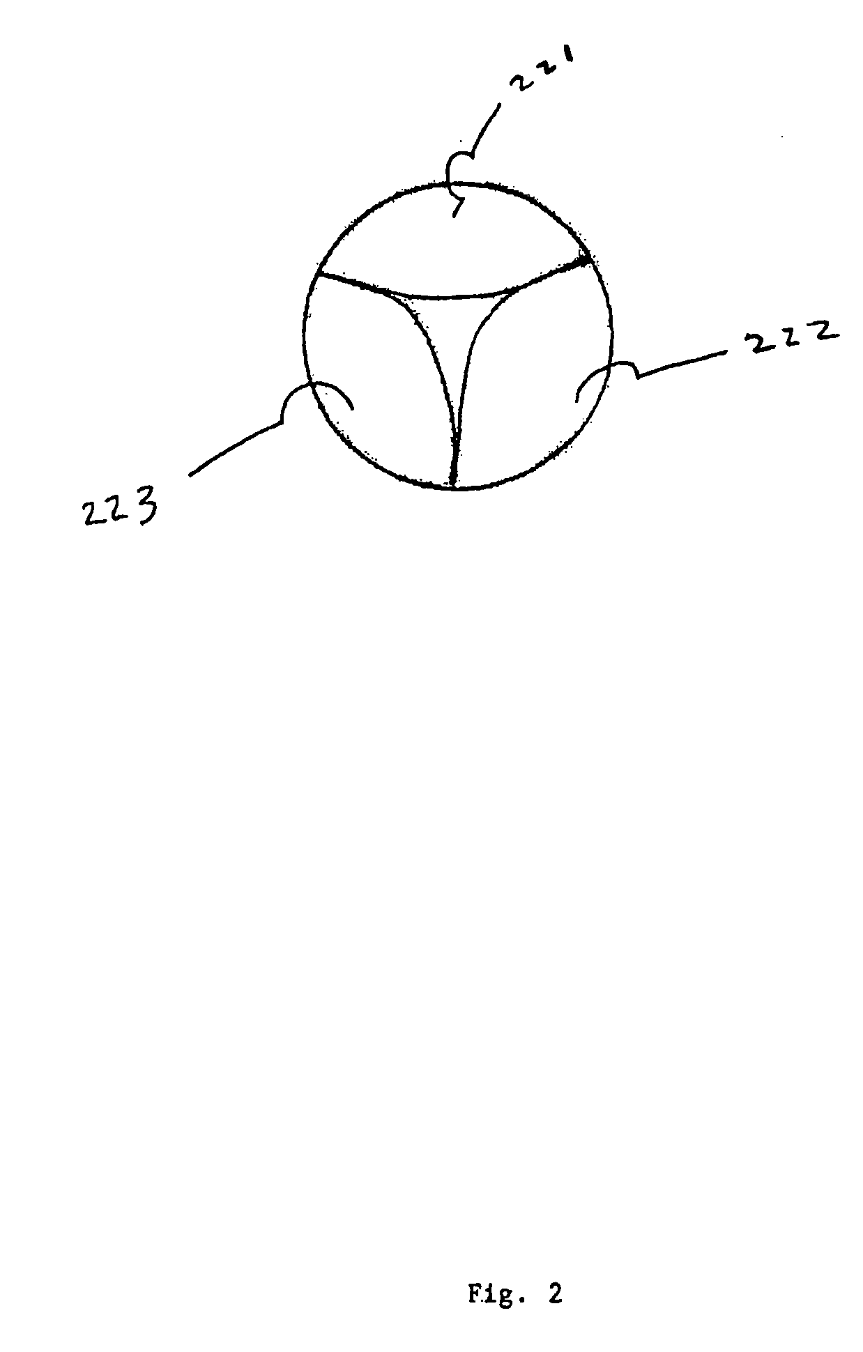
[0038]The present invention comprises a percutaneously implantable replacement heart valve and a method for making same. The artificial heart valve device of the present invention is capable of exhibiting a variable diameter between a compressed or collapsed position and an expanded position. A preferred embodiment of the replacement heart valve device according to the present invention is set forth in FIG. 5. The replacement heart valve device comprises a stent member 100 and a flexible valve means 200. The stent member 100 is preferably self-expanding, although balloon-expandable stents can be used as well, and has a first polygonal shape in its compressed or collapsed configuration and a second, larger polygonal shape in its expanded configuration. Referring to FIG. 1, the valve means 200 comprises a generally tubular portion 210 and, preferably, a peripheral upstanding cusp or leaflet portion 220. The valve means 200 is disposed within the cylindrical stent member 100 with the t...


PUM

PropertyMeasurementUnit
diameteraaaaaaaaaa
diameteraaaaaaaaaa
lengthaaaaaaaaaa

Abstract

A method of making a replacement heart valve device whereby a fragment of biocompatible tissue material is treated and soaked in one or more alcohol solutions and a solution of gluteraldehyde. The dried biocompatible tissue material is folded and rehydrated in such a way that forms a two- or three-leaflet / cusp valve without affixing of separate cusps or leaflets or cutting slits into the biocompatible tissue material to form the cusps or leaflets. After the biocompatible tissue material is folded, it is affixed at one or more points on the outer surface to the inner cavity or a stent.

Description

CONTINUITY INFORMATION[0001]This application is a divisional application of U.S. non-provisional patent application Ser. No. 10 / 887,688 filed on Jul. 10, 2004, which in turn is a continuation in part of U.S. non-provisional patent application Ser. No. 10 / 037,266 filed on Jan. 4, 2002. The applicants hereby claim the benefit under 35 U.S.C. §121 and 35 U.S.C. §120 based on said applications.BACKGROUND OF THE INVENTION[0002]1. Field of the Invention[0003]The present invention is in the field of heart valve replacement. More specifically, the present invention is directed to a method of making a percutaneously implantable replacement heart valve.[0004]2. Description of Related Art[0005]There have been numerous efforts in the field of heart valve replacement to improve both the durability and effectiveness of replacement heart valves as well as the ease of implantation. A brief description of heart valves and heart function follows to provide relevant background for the present inventio...

Claims


Application Information

Patent Timeline
Patent Type & Authority Applications(United States)
IPC IPC(8): A61F2/24A61F2/06A61F2/84A61F2/90
CPCA61F2/2412Y10T29/49412A61F2/2418A61F2/2436Y10S623/917A61F2/24A61F2/2475A61F2250/0039A61B8/12A61F2/2427A61F2220/0008A61F2220/0016A61F2220/0075A61F2/2433A61F2002/9534A61F2/2439A61F2210/0014A61F2/2415A61F2210/0076A61F2220/0025A61F2230/001A61F2230/0013A61F2230/0067A61F2230/0078A61F2230/0095A61F2240/001A61F2310/00371A61L27/3604A61L27/3683A61L27/3687A61L27/3691Y10S623/918
Inventor PANIAGUA, DAVIDINDUNI, EDUARDOMEJIA, CARLOSLOPEZ-JIMENEZ, FRANCISCOFISH, R. DAVID
Owner COLIBRI HEART VALVE
Why Eureka
Try Eureka