

R-Fe-B MICROCRYSTALLINE HIGH-DENSITY MAGNET AND PROCESS FOR PRODUCTION THEREOF
a high-density magnet, microcrystalline technology, applied in the direction of magnetic materials, inductance/transformer/magnet manufacturing, magnetic bodies, etc., can solve the problems of significant deterioration in properties, increased manufacturing costs, and poor productivity of microcrystalline high-density magnet obtained by hddr process, so as to achieve the effect of relatively easy and cost-effective production of r—fe—b based microcrystalline high-density magn
- Summary
- Abstract
- Description
- Claims
- Application Information
AI Technical Summary
Benefits of technology
Problems solved by technology
Method used
Image

Examples
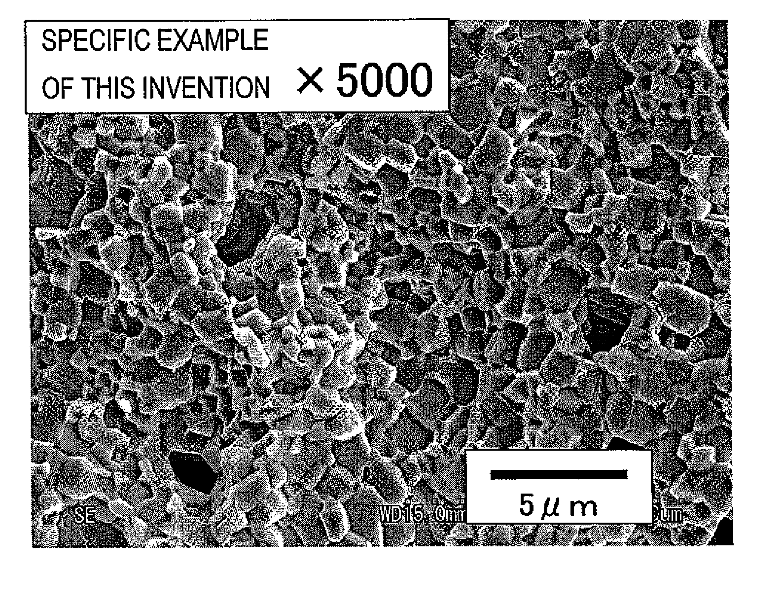
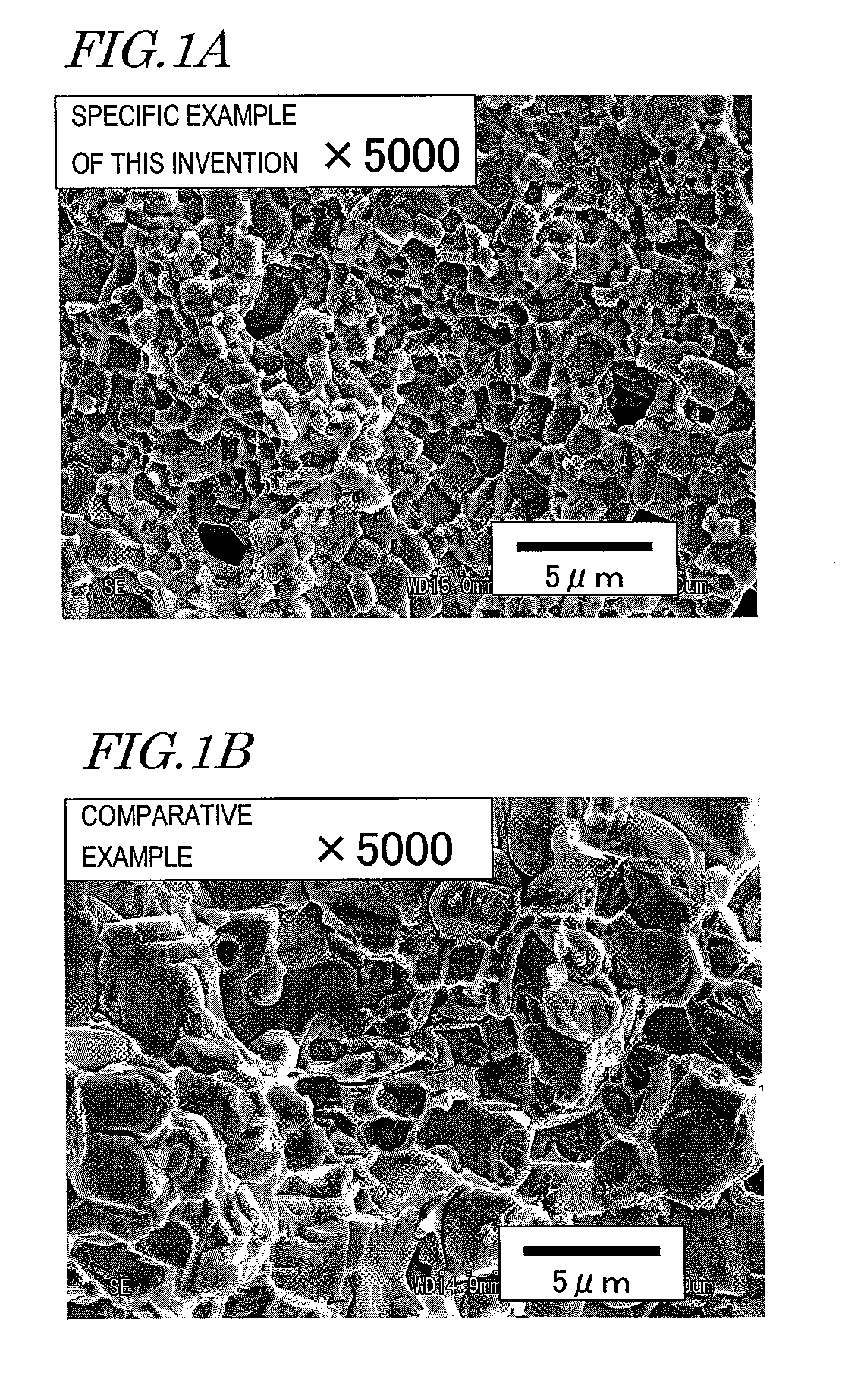
example 1
[0178]An alloy with a composition such as the one shown in the following Table 1 was provided to make a microcrystalline high-density rare-earth permanent magnet by the manufacturing process that has been described above as preferred embodiments of the present invention. In Table 1, the unit of the numerical values is at %. Hereinafter, a method for producing a magnet according to a first specific example of the present invention will be described.
TABLE 1AlloyNdFeCoBAlCuGaA15.9Balance1.06.20.50.10.1
[0179]First, a rapidly solidified alloy having the composition shown in Table 1 was made by a strip casting process. The rapidly solidified alloy thus obtained was coarsely pulverized by a hydrogen occlusion decrepitation process into a powder with particle sizes of about 425 μm or less, and then the coarse powder was finely pulverized with a jet mill, thereby obtaining a fine powder with a mean particle size of about 4.1 μm. As used herein, the “mean particle size” refers to an approxima...
example 2
[0190]Each of the samples obtained in Example 1 was cut and ground to as small a thickness as about 0.5 mm parallel to the alignment direction, magnetized with a pulse magnetic field of about 4.8 MA / m, and then had its magnetic properties measured with a vibrating sample magnetometer (VSM) (e.g., VSM5 produced by Toei Industry Co., Ltd). The results are shown in the following Table 3. In this case, the demagnetization curve of the specific example of a preferred embodiment of the present invention had no inflection point, which would be caused in a sintered magnet due to machining damage as will be described later, and (BH)max decreased by no more than about 2%. As a reference example, the results of measurements that were carried out with a BH tracer MTR-1412 (produced by Metron, Inc.) on a sample yet to be cut into thin pieces are also shown in the following Table 3:
TABLE 3JmaxBr(BH)maxHcJHkSample(T)(T)(kJ / m3)(kA / m)(kA / m)Example (already cut into thin1.211.19258940585pieces)Refere...
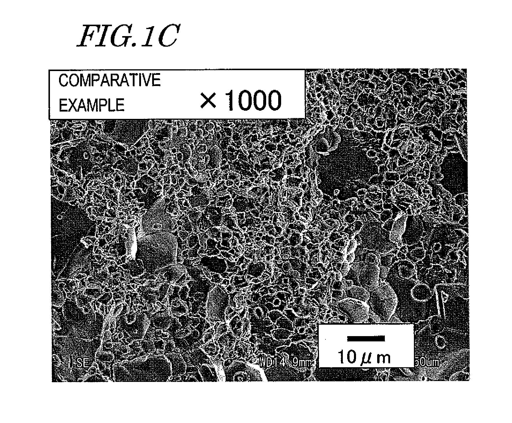
example 3
[0193]Next, the microcrystalline high-density magnet of the first specific example of a preferred embodiment of the present invention described above was pulverized with a mortar within an argon atmosphere and then classified, thereby obtaining a powder with particle sizes of about 75 μm to about 300 μm. Then, this powder was loaded into a cylindrical holder and fixed with paraffin while being aligned with a magnetic field of about 800 kA / m. The sample thus obtained was magnetized with a pulse magnetic field of about 4.8 MA / m and then its magnetic properties were measured with a vibrating sample magnetometer (VSM) (e.g., VSM5 produced by Toei Industry Co., Ltd). It should be noted that no anti-magnetic field correction was made. The results are shown in the following Table 4:
TABLE 4JmaxBr(BH)maxHcJAlloy(T)(T)(kJ / m3)(kA / m)A1.191.12188859
[0194]In Table 4, Jmax and Br were calculated on the supposition that the sample had a true density of about 7.60 g / cm3. It should be noted that Jmax...
PUM
| Property | Measurement | Unit |
|---|---|---|
| Grain size | aaaaa | aaaaa |
| Grain size | aaaaa | aaaaa |
| Temperature | aaaaa | aaaaa |
Abstract
Description
Claims
Application Information