Self-sensing stents, smart materials-based stents, drug delivery systems, other medical devices, and medical uses for piezo-electric materials

a smart materials and stent technology, applied in the field of stents, can solve the problems of complex interface between biomaterials and flowing blood, and achieve the effect of improving medical stent technology

Inactive Publication Date: 2009-02-05
VIRGINIA COMMONWEALTH UNIV
View PDF3 Cites 57 Cited by
  • Summary
  • Abstract
  • Description
  • Claims
  • Application Information

AI Technical Summary

Benefits of technology

[0005]This invention significantly improves upon medical stent technology and provides solutions for challenging problems discussed above. One objective of th

Problems solved by technology

Despite these changes, the complexity of the interface of b

Method used


Image

  • Self-sensing stents, smart materials-based stents, drug delivery systems, other medical devices, and medical uses for piezo-electric materials
  • Self-sensing stents, smart materials-based stents, drug delivery systems, other medical devices, and medical uses for piezo-electric materials
  • Self-sensing stents, smart materials-based stents, drug delivery systems, other medical devices, and medical uses for piezo-electric materials

Examples


example 1

[0054]In this example, “smart” biomaterials are used that allow their implantation and measurement of intravascular flow and pressure. This stent design is based on piezoelectric materials. Sensing capabilities are incorporated either intrinsic to the stent or coupled to the stent.

[0055]Once the stent of this example is placed in a patient, it is interrogated periodically to ensure that blood is flowing through the artery. Flow velocity and pressure are two variables that are targeted. This interrogation is accomplished remotely. An antenna is integrated with the device to take the sensor signal and transfer the signal into an electromagnetic signal, which is then transmitted outside the body and picked up remotely.

[0056]Based on these principles, it is possible to monitor other aspects of myocardial function from the stent. This includes but is not limited to contractility parameters from the coronary artery-myocardial surface.

[0057]Because some stents are placed angiographically u...

example 2

[0077]In this Example, research was focused on the use of PVDF and its ability to provide a link between mechanical stimulus and electrical output. PVDF refers to Poly(vinylidene fluoride), which is a commercially available polymer, demonstrates piezoelectricity, has high resistance to both heat and electricity, and is highly non-reactive. Previous application of PVDF include: electrical and chemical insulators, speakers, strain gauges, voltage sources, and various sensor applications.

[0078]An experimental setup was established according to FIG. 4.

[0079]The following test was performed to test the effect of the flow pressure range on the voltage response of the PVDF. The test was performed using PVDF in a coated configuration at a frequency of 1 Hz. Data was taken at each range and the average of the peak to peak voltage of 5 cycles was calculated.

[0080]The results (see FIGS. 7-8B) show that an increase in the pressure range brings about an increase in the PVDF voltage response. Fur...

example 3 (

SELF-POWERED STENT)

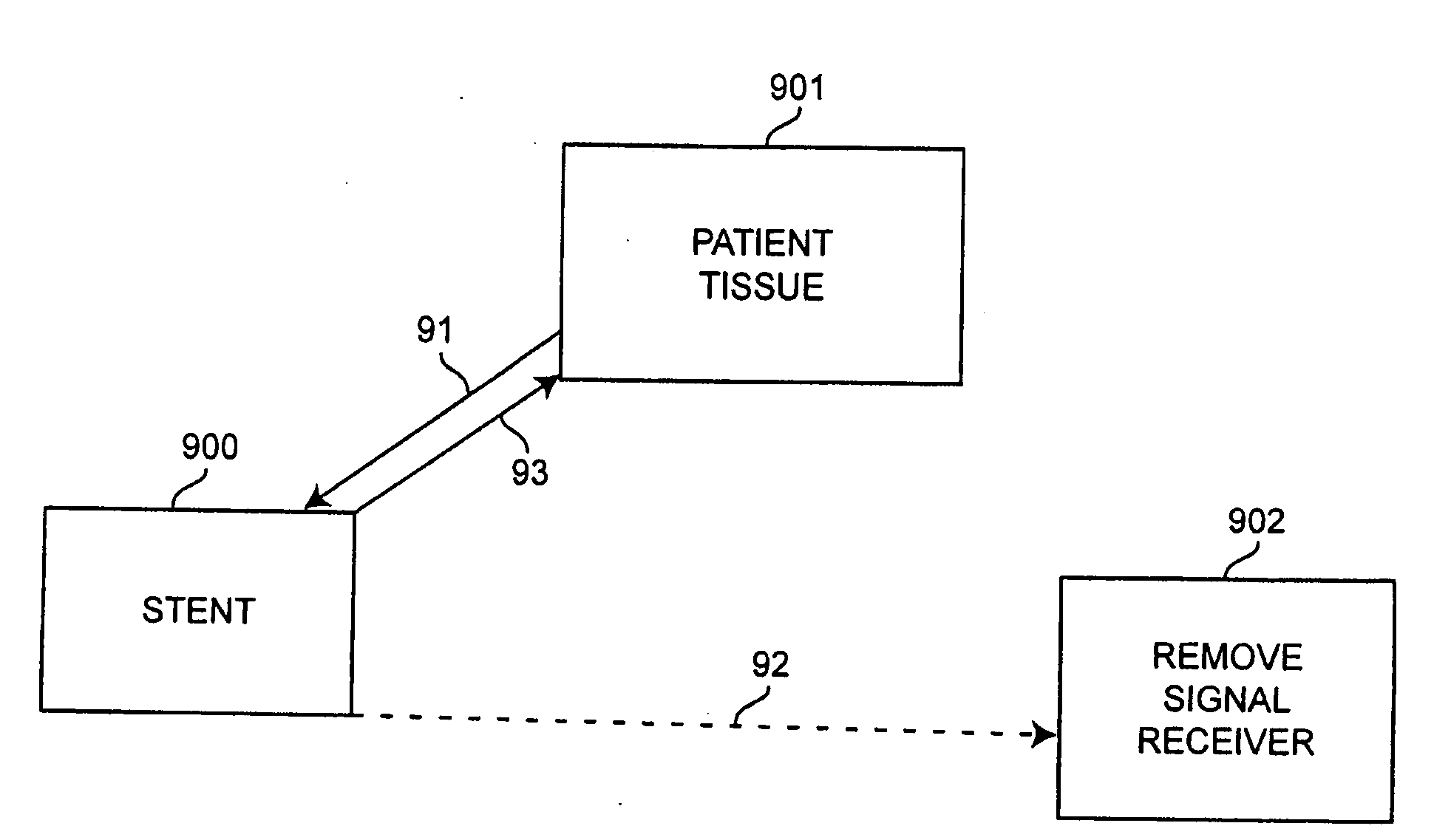
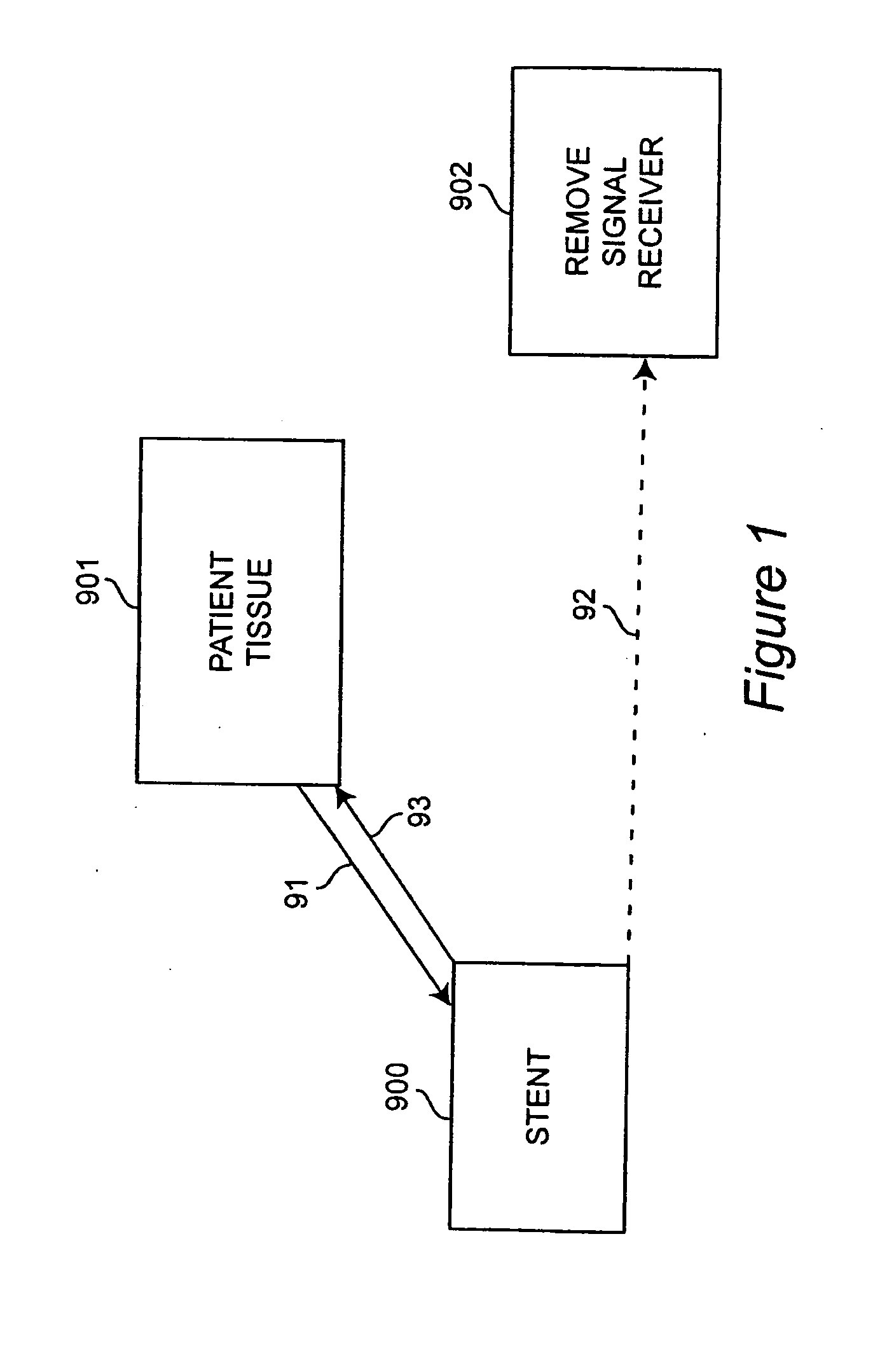
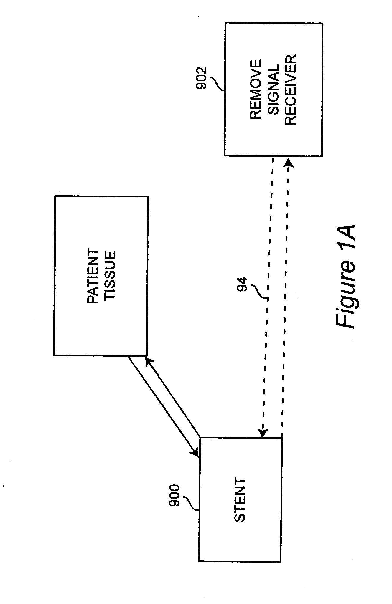
[0083]A piezo-electric material-containing stent is fitted with energy conversion and / or energy storage components by which piezo-electrically obtained energy (i.e., energy obtained via the piezo-electrical interaction with the tissue in which the product will be implanted) is converted to electrical signals and / or stored. Examples of energy conversion and energy storage components are, e.g., capacitors, batteries, diodes, transformers, etc.

[0084]Circuitry is included for using the stored energy to power one or more energy-using components (such as, e.g., a releasing mechanism on a drug-containing reservoir; an antenna; etc.) contained in, on, contiguous, near or separate from the stent.


PUM


Abstract

A medically implantable stent comprising at least one piezo-electric material may be active, such as by one or more of: delivering an anti-coagulant or other therapeutic effect to a patient in which it is implanted; powering itself; and/or sending an outbound electronic signal to a remote device. When a stent can send such an outbound signal, a physician may non-invasively ascertain the condition of the tissue near the stent.

Description

FIELD OF THE INVENTION[0001]The invention generally relates to medicine, and especially relates to stents.BACKGROUND OF THE INVENTION[0002]Conventionally, stents have been either metallic or polymeric. The stent is inserted to improve flow through an artery by maintaining patency of the artery. Stents are inserted in the artery and expanded to shape by means of an inflatable balloon. Stents are undergoing many changes in designs including the materials from which they are made. Examples include new drug eluting stents which secrete compound from an internal part or luminal surface to prevent clotting. Other designs include incorporating special materials such as NiTl metal, a shape memory alloy (SMA) that exhibits large strains when traversing its transition temperature. The SMA stent can be inserted in the vessel, and as result of experiencing body temperature, enlarges to the required dimensions.[0003]Despite these changes, the complexity of the interface of biomaterials with flow...

Claims


Application Information

Patent Timeline
IPC IPC(8): A61F2/06A61F2/82
CPCA61B5/0031A61B5/01A61B5/0215A61B5/026A61N1/3785A61F2/82A61L31/16A61L2300/42A61L2300/424A61B2560/0214
Inventor WARD, KEVINOUNAIES, ZOUBEIDAVETROVEC, GEORGE
Owner VIRGINIA COMMONWEALTH UNIV
Why Eureka
Try Eureka