Probe card, semiconductor inspecting apparatus, and manufacturing method of semiconductor device
a manufacturing method and semiconductor technology, applied in the direction of individual semiconductor device testing, semiconductor/solid-state device testing/measurement, instruments, etc., can solve the problems of short-circuit between wires and foreign objects, material with lower dielectric constant damage, and contact resistance becoming unstabl
- Summary
- Abstract
- Description
- Claims
- Application Information
AI Technical Summary
Benefits of technology
Problems solved by technology
Method used
Image
Examples
first embodiment
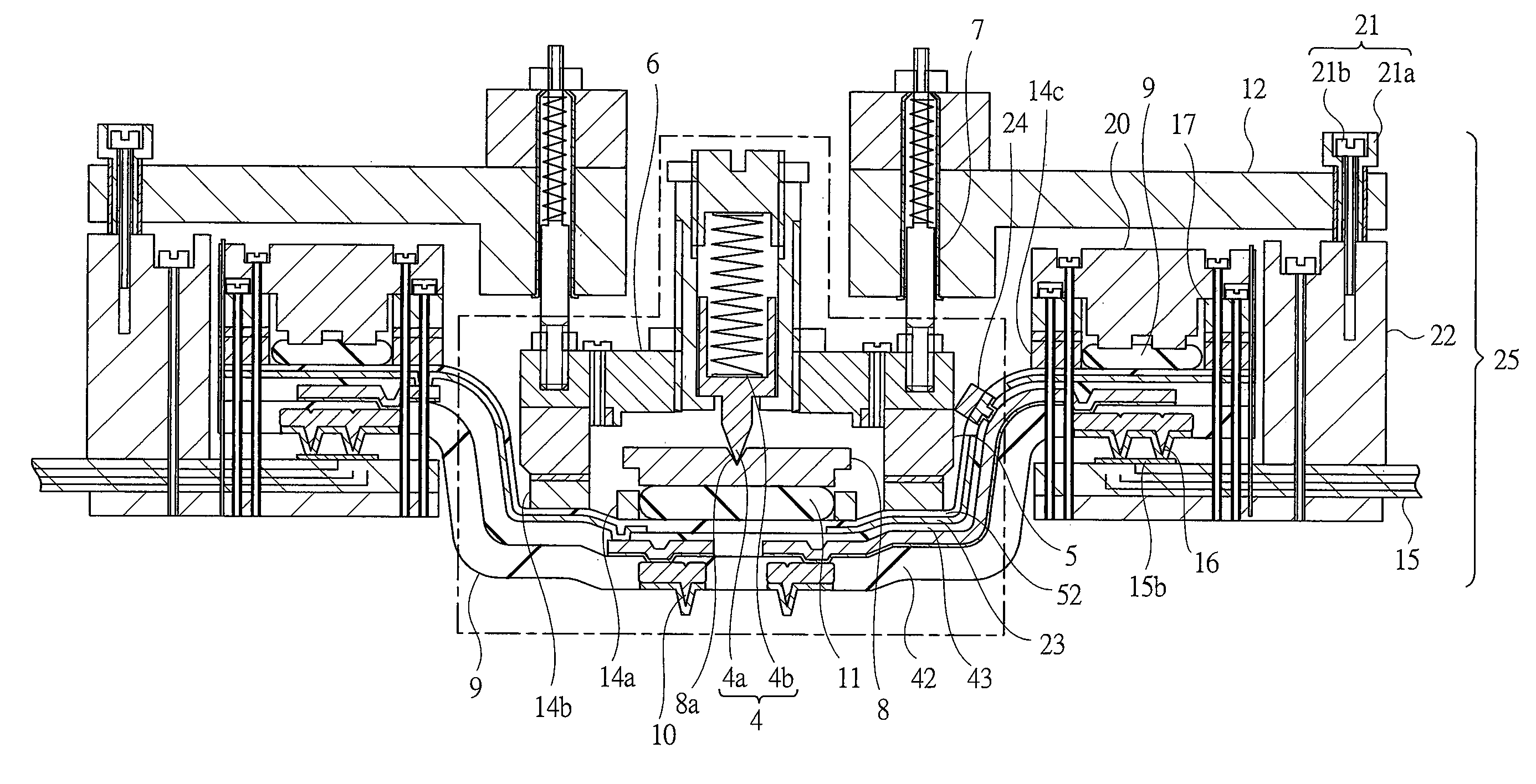
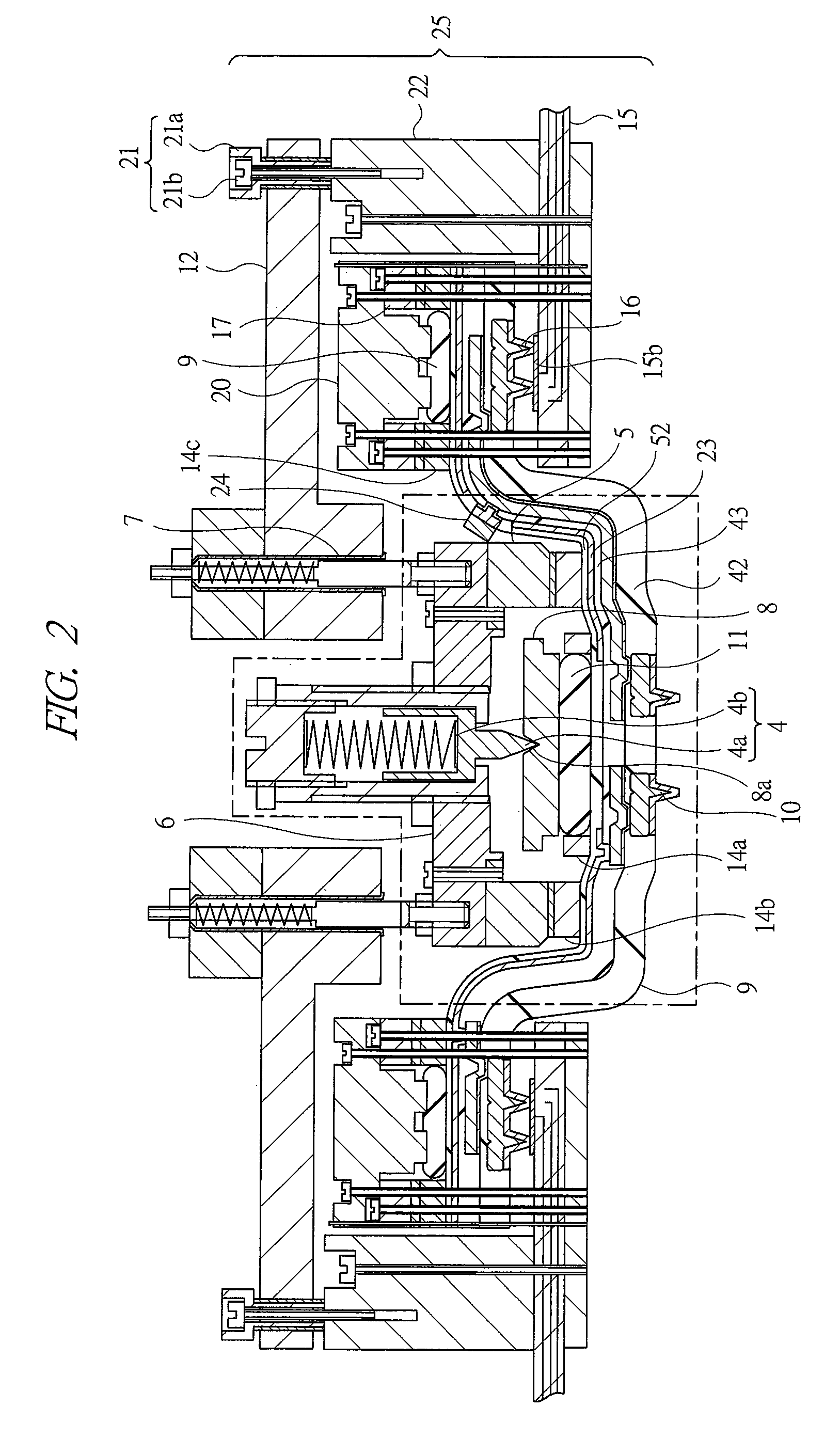
[0156]FIG. 2 is a cross sectional view showing a main portion of a probe card according to a first embodiment, FIG. 3 is a perspective view showing main parts shown in FIG. 2 in an exploded manner, and FIG. 4 a sectional view showing assembling of main parts of the probe card shown in FIG. 2 in an exploded manner. A probe card according to the first embodiment will be explained with reference to FIGS. 2 to 5.
[0157]The probe card according to the first embodiment includes a spring plunger 4, a frame 5, an intermediate plate 6, a plurality of guide pins 7, and the like.
[0158]The spring plunger (means for imparting a pressing force to a probe sheet center) 4 is fixed to a central portion of the intermediate plate 6 such that it is adjustable in its height direction, it has a protrusion portion 4a at its lower end to serve as a center pivot, and it is provided with a spring 4b imparting pressing force to a probe sheet 9 via a pushing piece 8 movable about a distal end of the protrusion ...
second embodiment
[0175]FIG. 7 is a cross sectional view showing a main portion of a probe card according to a second embodiment. In the first embodiment, the case that the ground wire 23 is formed on the probe sheet 9 and the chip capacitor 24 is attached thereon has been shown (see FIG. 2 and FIG. 6), but when a high-speed electric inspection signal is not required, as shown in FIG. 7, such a configuration that the ground wire 23, the chip capacitor 24, or the both may be omitted may be adopted.
[0176]In a configuration of a probe card explained below, such a configuration can be adopted depending on a speed of an inspection signal that the ground wire 23 or the chip capacitor 24 has been omitted like the above. The double screw 21 for fine adjustment of inclination (see FIG. 2) or the spacer 22a (see FIG. 6) can be used according to needs and it may be omitted, of course.
[0177]In FIG. 2 shown in the first embodiment, the example where the metal film 14a and the metal film 14b on a region correspond...
third embodiment
[0180]FIG. 8 is a cross sectional view showing a main portion of a probe card according to a third embodiment and FIG. 9 is a sectional view of a main portion showing the vicinity of a contact terminal 10 of the probe card according to the third embodiment in an enlarged manner. The probe card according to the third embodiment will be explained with reference to FIGS. 8 and 9.
[0181]In the probe sheet 9, when a connection electrode portion 10b on which individual contact terminals 10 are formed and a wire material 26 are connected to each other, via holes are utilized in the first embodiment, but, in the third embodiment, via holes are omitted and a wire material 26 is directly formed on the surface of the connection electrode portion 10b (see FIG. 9). The other configuration of the third embodiment is similar to those of the first embodiment.
[0182]According to a probe sheet structure 25c of the third embodiment with such a structure, since a structure where via holes are omitted is ...
PUM
 Abstract
Description
Claims
Application Information
 - R&D
- Intellectual Property
- Life Sciences
- Materials
- Tech Scout
- Unparalleled Data Quality
- Higher Quality Content
- 60% Fewer Hallucinations
Browse by: Latest US Patents, China's latest patents, Technical Efficacy Thesaurus, Application Domain, Technology Topic, Popular Technical Reports.
© 2025 PatSnap. All rights reserved.Legal|Privacy policy|Modern Slavery Act Transparency Statement|Sitemap|About US| Contact US: help@patsnap.com


