Recording layer for optical information recording medium, optical information recording medium, and sputtering target for optical information recording medium

a technology of optical information and recording medium, which is applied in the field of optical information storage media recording layers and sputtering targets, and recording layers for can solve the problems of low c/n ratio of optical storage media, low corrosion resistance of optical information storage media, and gradual deterioration of metallic recording layers in writing and reading properties for a longer time period, etc., to suppress the oxidation of the recording layer and improve corrosion resistance. , the effect of low melting poin

Inactive Publication Date: 2009-02-19
KOBE STEEL LTD
View PDF1 Cites 11 Cited by
  • Summary
  • Abstract
  • Description
  • Claims
  • Application Information

AI Technical Summary

Benefits of technology

[0057]In the tin-based alloy for use in the recording layer for optical information storage media according to the fifth embodiment of the present invention, tin (Sn) as a matrix has a low melting point and makes it possible to create recording marks upon irradiation with a laser beam even at a low power. In addition, the elements belonging to Groups 4a, 5a, 6a, and 7a of the Periodic Table of Elements, and Dy, Sm, and Ce are more susceptible to oxidation than tin, and the additional elements are oxidized to form a dense oxide film on the surface of the recording layer composed of the tin-based alloy, and this suppresses the oxidation of the recording layer, improves corrosion resistance, and retains over long period of time high reflectivity which the tin-based alloy originally possesses. In addition, these elements effectively retain surface smoothness of the entire recording layer composed of the tin-based alloy, because they have melting points higher than that of tin.
[0058]Among the above-mentioned elements, platinum (Pt) is more resistant to oxidation than tin, and oxygen and moisture passing through a resinous substrate and/or a cover layer initially oxidize tin prior to platinum. Platinum, ho...

Problems solved by technology

Although the known techniques of recording information using the hole creating recording system improve recording properties such as low thermal conductivity, high initial reflectivity, and good creation of recording marks, durability of optical storage media is still poor under high temperature and high humidity conditions.
The recording layers for optical information storage media also suffer from a low C/N ratio as is mentioned above, in addition to poor durability ...

Method used


Image

  • Recording layer for optical information recording medium, optical information recording medium, and sputtering target for optical information recording medium
  • Recording layer for optical information recording medium, optical information recording medium, and sputtering target for optical information recording medium
  • Recording layer for optical information recording medium, optical information recording medium, and sputtering target for optical information recording medium

Examples


experimental example 1

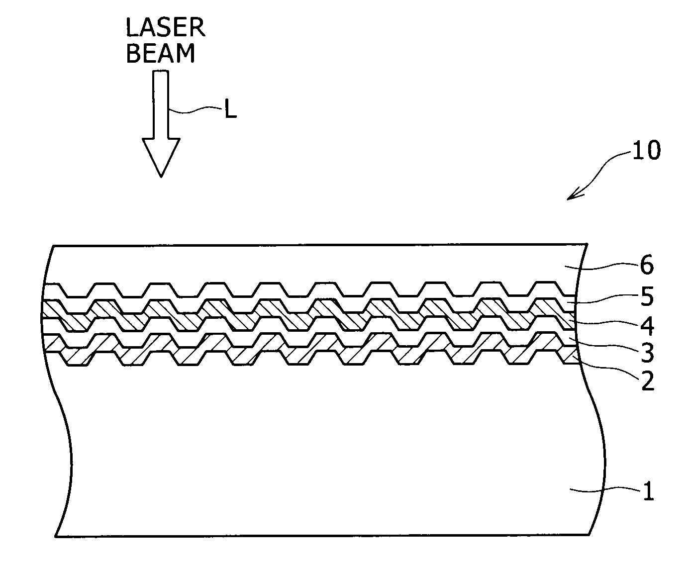
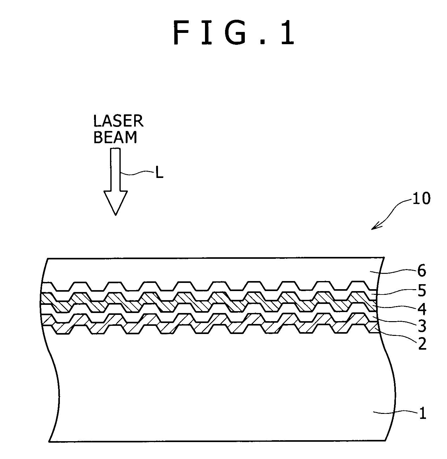
[0212]Experimental Example 1 relates to recording layers for optical information storage media according to the first embodiment of the present invention.

[0213]Preparation Example of Samples

[0214]Samples of various thin films of tin-based alloys including Sn—Nd alloy thin films, Sn—Gd alloy thin films, and Sn—La alloy thin films shown in Table 1 were deposited in the following manner, and these were examined for the initial reflectivity, creation of recording marks, and durability. For comparison, a pure tin thin film was deposited and was examined for the properties in the same way.

[0215]Deposition of Tin-based Alloy Thin Films and Pure Tin Thin Film

[0216]Each of a pure tin thin film and a series of thin films of tin-based alloys was deposited on a transparent polycarbonate substrate having a thickness of 0.6 mm and a diameter of 120 mm using a pure tin sputtering target. The thin films of tin-based alloys were deposited using a composited sputtering target with chips of alloy elem...

experimental example 2

[0242]Experimental Example 2 relates to recording layers for optical information storage media according to the second embodiment of the present invention.

[0243]Preparation Example of Samples

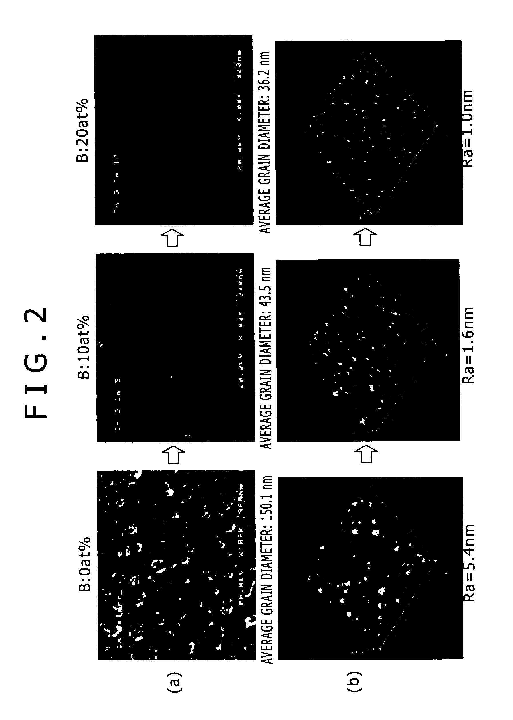
[0244]Samples of various thin films of tin-based alloys including Sn—B alloy thin films, Sn—B—Y alloy thin films, and Sn—B—In alloy thin films shown in Table 2 were deposited in the following manner, and these were examined for the initial reflectivity, creativity of recording marks, durability, surface roughness Ra, and media noise. For comparison, a pure tin thin film was deposited and was examined for the properties in the same way.

[0245]Deposition of Tin-based Alloy Thin Films and Pure Tin Thin Film

[0246]Each of a pure tin thin film and a series of thin films of tin-based alloys was deposited on a transparent polycarbonate substrate having a thickness of 0.6 mm and a diameter of 120 mm using a pure tin sputtering target. The thin films of tin-based alloys were deposited using a composited sp...

experimental examples 3 to 5

[0284]Experimental Examples 3 to 5 below relate to recording layers for optical information storage media according to the third embodiment of the present invention.


PUM

PropertyMeasurementUnit
Thicknessaaaaaaaaaa
Thicknessaaaaaaaaaa
Thicknessaaaaaaaaaa

Abstract

Provided is a recording layer for optical information storage media, which not only excels in initial reflectivity and creativity of recording marks, but also extremely excels in durability under high temperature and high humidity conditions, and which can be adequately applied to next-generation optical discs using blue-violet laser. The recording layer for optical information storage media is a recording layer to create recording marks upon irradiation with a laser beam. This recording layer is composed of a tin-based alloy containing a total of 1.0 atomic percent or more and 15 atomic percent or less of at least one selected from neodymium (Nd), gadolinium (Gd), and lanthanum (La).

Description

TECHNICAL FIELD[0001]The present invention relates to recording layers and sputtering targets for optical information storage media, as well as optical information storage media using the same. The recording layers for optical information storage media according to the present invention can be used not only for current compact discs (CDs) and digital versatile discs (DVDs) but also for next-generation optical information storage media such as HD DVDs and Blu-ray Discs, and suitably used for write-once optical information storage media, particularly for optical information storage media using blue-violet laser.BACKGROUND ART[0002]Optical information storage media (optical discs) are roughly categorized by the writing and reading system into three main types, i.e., read-only, rewritable, and write-once optical discs.[0003]In write-once optical discs among these discs, data is recorded by principally utilizing changes in properties of material in the recording layer irradiated with a l...

Claims


Application Information

Patent Timeline
IPC IPC(8): G11B7/26G11B7/243G11B7/258
CPCC22C13/00G11B7/243G11B2007/24312G11B2007/24304G11B2007/2431G11B7/258
Inventor FUJII, HIDEOIDO, TATEWAKITAUCHI, YUKISAKODA, NAOKAZU
Owner KOBE STEEL LTD
Why Eureka
Try Eureka