Secondary light source

a technology of secondary light source and light source, which is applied in the field of secondary light source, can solve the problems of poor efficiency, generating relatively high losses in the form of waste heat, and difficulty in coupling light into thin optical waveguides, so as to increase the efficiency of secondary light source and increase conversion efficiency. the effect of the distal end

Inactive Publication Date: 2009-03-05
CARL ZEISS SURGICAL
View PDF5 Cites 81 Cited by
  • Summary
  • Abstract
  • Description
  • Claims
  • Application Information

AI Technical Summary

Benefits of technology

[0020]In one advantageous development of the secondary light source, a dichroic mirror coating is adjacent to the phosphor region in the direction of the proximal end of the optical waveguide. Said mirror coating is embodied such that it reflects light propagating in the direction of the proximal end. It is thereby possible to prevent light that arises in the converter phosphor from being conducted in the direction of the proximal end of the optical waveguide instead of being emitted from the distal end. The intensity of the converted light at the distal end can therefore be increased with the aid of the dichroic mirror coating in comparison with an optical waveguide not having such a mirror coating which further increases the efficiency of the secondary light source. In particular, the mirror coating can also be embodied such that it is highly reflective only for the converted light, but transmissive for the original narrowband light.
[0021]Furthermore, it is possible to arrange a partly transmissive mirror coating at the output of the distal end of the optical waveguide, which mirror coating is highly reflective for phototoxic wavelength components of the original narrowband light, but transmissive for the non-phototoxic components and the converted light. In this way, the phototoxic components can be kept away from the tissue e.g. when the secondary light source is used in an endoilluminator. At the same time, the reflected portion of the light is fed to the converter phosphor again, which increases the conversion efficiency. An almost hundred percent conversion can thus be achieved particularly in interaction with the above-mentioned mirror coating preventing the propagation of light in the direction of the proximal end of the optical waveguide.

Problems solved by technology

In the case of LEDs as light sources, LEDs of different colors have to be used, which makes it more difficult to couple the light into the optical fibers.
Although the hitherto customary endoilluminators based on halogen, xenon or metal halide lamps can be varied in their color by means of filters, they have a poor efficiency and generate relatively high losses in the form of waste heat.
Moreover, since the emissive area is relatively large, the light can also only be coupled into the thin optical waveguides with difficulty or ineffectively.
This, too, again enlarges the emissive area and thus makes it more difficult to effect coupling into thin optical waveguides.
However, as already mentioned, coupling LED light into the optical fiber often poses problems with regard to the efficiency and the luminous power, which adversely influences the intensity of the light at the output end of the fiber, that is to say the intensity of the secondary light source.
In addition the emission at the distal end of the optical waveguide, as mentioned further above, is not optimal and therefore requires further measures, if appropriate.

Method used


Image

  • Secondary light source
  • Secondary light source
  • Secondary light source

Examples


Embodiment Construction

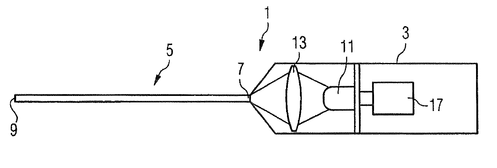
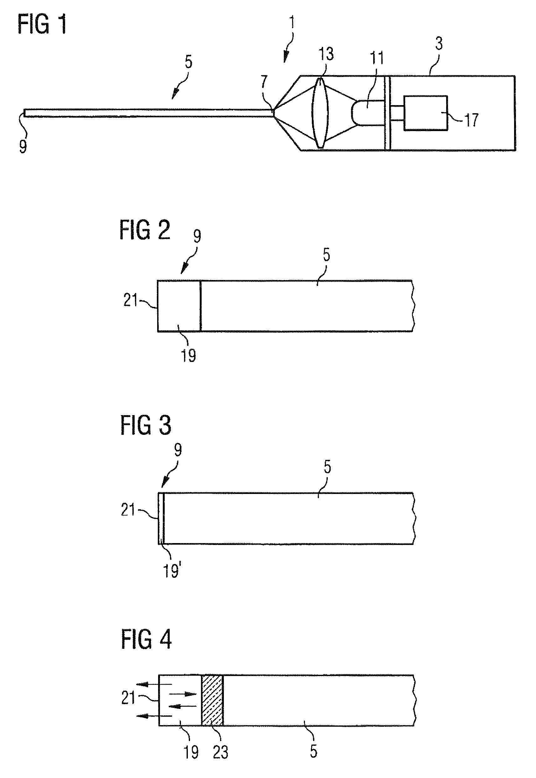
[0034]FIG. 1 shows an endoilluminator 1 in a highly schematic illustration as an exemplary embodiment of a medical illumination device comprising a secondary light source according to the invention. The endoilluminator 1 comprises a handle 3 and a glass fiber rod 5. The glass fiber rod 5 serves as an optical fiber having a proximal end 7, into which is coupled light from a primary light source 11 arranged in the interior of the handle 3, and a distal end 9, to which the light coupled in is guided and from which said light emerges.

[0035]In the present exemplary embodiment, the glass fiber rod is embodied as a monomode fiber. The diameter of the glass fiber rod is therefore very small (8-10 μm), such that it can be inserted through just small openings into the body, whereby trauma can be minimized.

[0036]Although not explicitly illustrated in the figures, the glass fiber rod 5 is surrounded by a sheath, which can likewise be thin. The latter additionally can be surrounded by a protecti...


PUM


Abstract

A secondary light source is provided comprising a narrowband light source (11) that emits narrowband light as a primary light source, an optical waveguide (5) having a proximal and a distal end (9), a coupling-in device (13) that is arranged at the proximal end (7) of the optical waveguide (5) and serves for coupling the narrowband light into the optical waveguide (5), and a phosphor region (19) that is present at or before the distal end (9) of the optical waveguide (5), said phosphor region being provided with a converter phosphor. The converter phosphor of the phosphor region (19) is chosen with respect to the narrowband light emitted by the narrowband light source (11) in such a way that it increases the wavelength of at least part of the narrowband light.

Description

BACKGROUND OF THE INVENTION[0001]1. Field of the Invention[0002]The present invention relates to a secondary light source and also to a medical illumination device and an optical coherence tomography device (OCT).[0003]2. Description of the Related Art[0004]In medical technology, so-called endoilluminators are often used in order, for example in the case of interventions on the eye, to illuminate the latter internally which is of importance particularly in the case of interventions on the rear portion of the eye. Such endoilluminators can also be used in other microsurgical or endoscopic interventions in body cavities.[0005]It is standard practice here for the light from halogen, xenon, metal halide lamps or from high power LEDs to be coupled into optical fibers and introduced into the body cavities by means of corresponding handpieces, so called applicators. In this case, the light sources are intended to be as small as possible in order to couple the light into the optical wavegui...

Claims


Application Information

Patent Timeline
Patent Type & Authority Applications(United States)
IPC IPC(8): G02B21/00A61B1/06H01L33/00H01L33/50
CPCA61B1/00165A61B1/00172A61B1/0653A61B3/0008A61B3/102G02B6/0008A61B19/5202A61B2019/5206G02B6/0003G02B6/0006A61B5/0066A61B90/30A61B2090/306
Inventor NAHM, WERNERMATZ, HOLGERBAUSEWEIN, MARKUSREIMER, PETER
Owner CARL ZEISS SURGICAL
Why Eureka
Try Eureka