
Piezoelectric materials based on flexoelectric charge separation and their fabrication

a technology of flexoelectric charge separation and piezoelectric materials, applied in the field of piezoelectric materials, can solve the problems of difficult to find any better materials, difficult in conventional piezoelectrics to break the connection between direct and converse effects, and severe limits on material choices available, etc., to achieve the effect of not significantly reducing the stress gradient, easy fabrication, and high sensitivity

Inactive Publication Date: 2009-03-12
PENN STATE RES FOUND
View PDF17 Cites 54 Cited by
  • Summary
  • Abstract
  • Description
  • Claims
  • Application Information

AI Technical Summary

Benefits of technology

[0017]Examples of the present invention relate to improved assembly processes allowing fabrication of high sensitivity multilayer flexoelectric piezoelectric materials, such as ceramics materials. Unlike conventional piezoelectric materials, centrosymmetric materials can be used, allowing a much wider range of materials to be used, and allowing lead-free devices to be readily fabricated. Flexoelectric piezoelectric materials may generate an electric potential in response to an applied force due to the provision of shaped elements within the material. An applied force generates a stress (or strain) gradient within the shaped elements, for example due to a cross-sectional area in a plane normal to the force direction that varies along the force direction. The stress gradient, in combination with the flexoelectric coefficient of the material, induces the electric potential. In such cases, a shaped element of a first material is preferably surrounded by a second material of lesser elastic constant (which may be termed a soft material), so that the stress gradient is not significantly reduced by the presence of the second material. The first material may be a ceramic, and the second material may be a non-ceramic material such as air, a polymer, or some combination of soft materials. Such materials may be used to create improved sensors, and devices for converting mechanical energy (such as vibrational energy) into electrical energy.
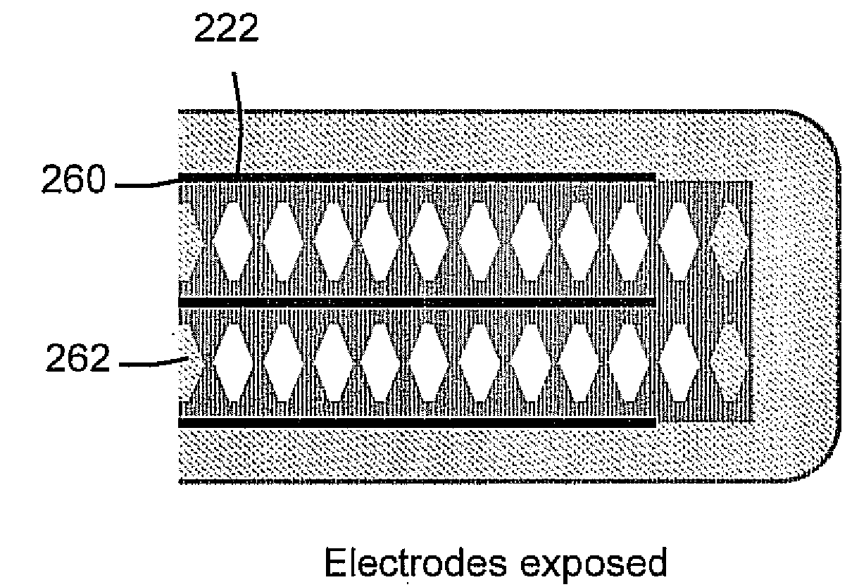
[0021]A multilayer structure may include a generally equal number of shaped elements arranged in each of two orientations, a first orientation and a second orientation that is a mirror image of the first orientation (e.g. reflected in a plane parallel to the base). Improved resonance properties are available, as slight variations in the position of the center of mass on application of e.g. an oscillatory force or electrical field can be avoided.
[0026]In other examples, the first and second materials have electrical permittivities differing by greater than one order of magnitude, more particularly greater than two orders of magnitude. In these examples, a field gradient at an interface that is at an oblique angle (i.e. not parallel or orthogonal) to the direction of an applied field allows a strong flexoelectrically induced converse piezoelectric effect to be observed.
[0033]The template may be fabricated by forming a mask by precision machining a replica of the shaped element into a non-ceramic material, such as a plastic, metal, dielectric material, and the like. The composition of the mask is not critical, but machining is facilitated by avoiding the need to machine a hard ceramic material. The mask fabrication may be relatively time consuming and expensive, for example due to the use of a precision machining tool. In some examples of the present invention, one or more masks (for example, a pair of masks, or a mask and a planar element) can be used to forming a mold, allowing the template to be created using the mold, the template including a negative replica of the desired shaped elements. In this way, a single mold can be easily used to make numerous templates, and the templates can be sacrificed during fabrication.
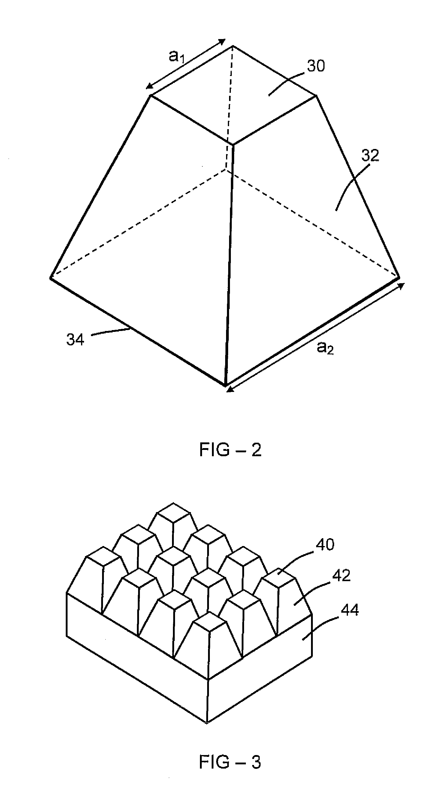
[0037]An example flexoelectric piezoelectric apparatus comprises a first shaped element, configured so as to provide a first stress gradient when a force is applied to the apparatus, and a second shaped element configured so as to provide a second stress gradient when the force is applied to the apparatus. The first and second shaped elements may be configured in a generally mirror-image (e.g. 180 degree rotation) configuration relative to each other, so as to obtain first and second stress gradients that are oppositely directed (i.e. the stress increases in a particular direction in the first element and decreases in the same or parallel direction in the second element). The first shaped element and second shaped element may be pyramids, truncated pyramids, cones, and truncated cones. An example apparatus may comprise a plurality of first shaped elements, and a plurality of second shaped elements. The numbers of first and second elements may be approximately equal, for example a number of truncated pyramids aligned in a given orientation and a similar number aligned in the opposite direction. This allows improved resonance properties of an apparatus, as the device can be configured so that the center of mass does no significantly move in response to applied electric fields or forces, compared with the movement observed in conventional piezoelectric devices.

Problems solved by technology

Further, the conventional belief is that piezoelectric materials must be non-centrosymmetric, or at least contain a non-centrosymmetric component, which severely limits the material choices available.
It has proved difficult to find any better material, using conventional approaches.
It is impossible in conventional piezoelectrics to break the connection between direct and converse effects.
It is also difficult to make either thick or thin film piezoelectrics of high sensitivity.
Most current piezoceramics are based on lead containing perovskite structure compositions, and as noted above this is less than ideal.

Method used


Image

  • Piezoelectric materials based on flexoelectric charge separation and their fabrication
  • Piezoelectric materials based on flexoelectric charge separation and their fabrication
  • Piezoelectric materials based on flexoelectric charge separation and their fabrication

Examples


example composite

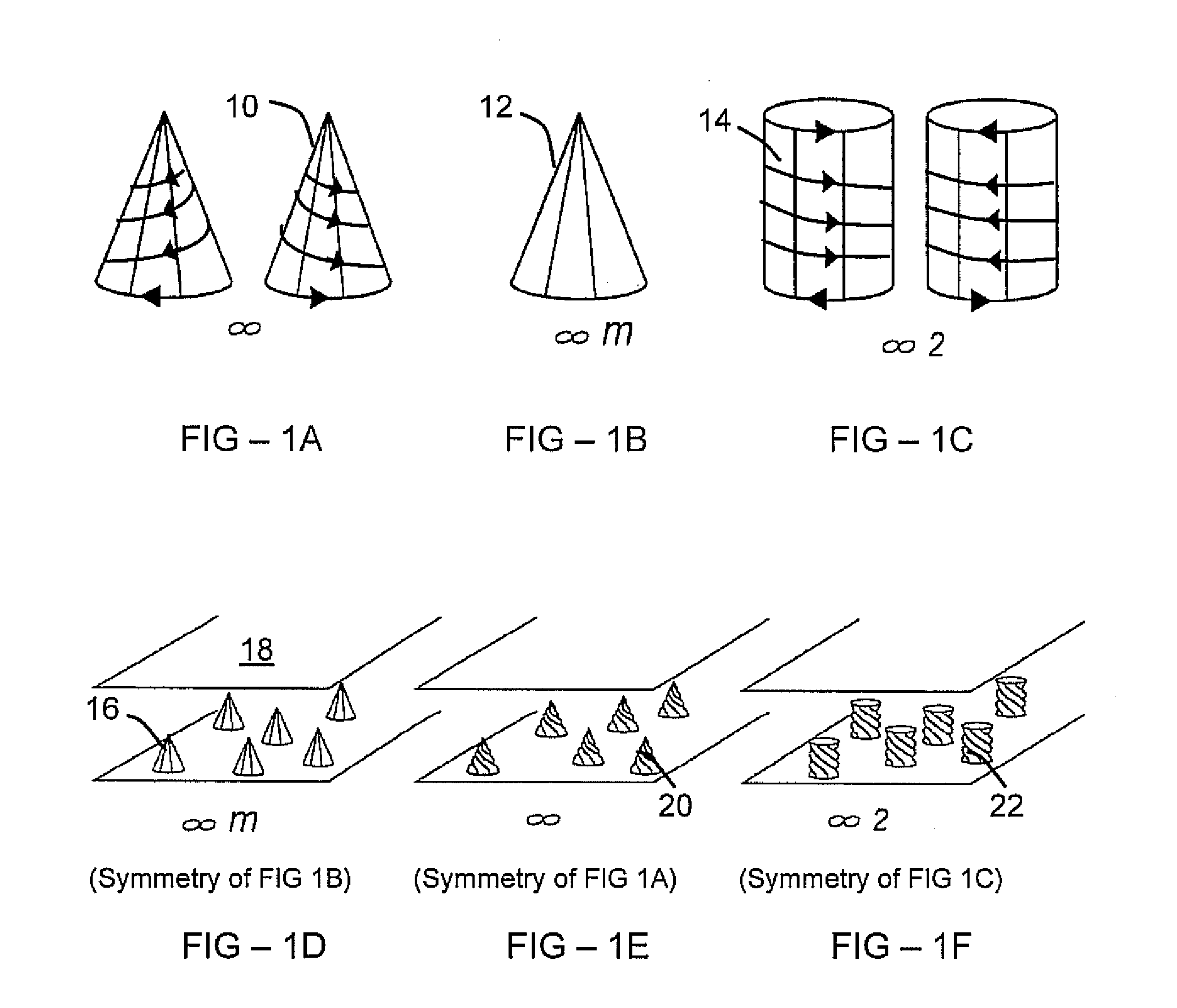
[0066 materials according to embodiments of the present invention include a first material having a shape, for example a truncated cone (frustoconical shape), other shape representing the symmetry of Curie group ∞m as shown in FIG. 1B, or other shape allowing piezoelectric coefficients within an isotropic material. Other examples include a simple 0-3 composite preserving ∞m piezoelectrically active symmetry. Other examples include pyramids (in particular truncated pyramids), and the like. The base shape of a pyramid may be triangular, square, rectangular, or other shape.

[0067]An example composite comprises oriented truncated pyramidal or truncated conical shaped elements of a first material in a matrix of a second material, where the two materials are elastically dissimilar. In representative examples, the first and second materials are both dielectrics, and the first or second material may be a fluid such as air.

[0068]Oriented shaped elements having at least one surface angled with...


PUM

PropertyMeasurementUnit
Angleaaaaaaaaaa
Electrical conductoraaaaaaaaaa
Mechanical propertiesaaaaaaaaaa

Abstract

An example flexoelectric piezoelectric material has a piezoelectric response, which may be a direct piezoelectric effect, a converse piezoelectric effect, both effects, or only one effect. A flexoelectric piezoelectric material comprises shaped elements of a material, which may be a substantially isotropic and centrosymmetric material. The shaped elements, such as cones, pyramids, wedges, or other tapered elements, may provide an electrical response in response to stress or strain gradients due to a flexoelectric effect in the material, and may provide a mechanical response in response to electric field gradients. Examples of the present invention include improved methods of fabricating devices comprising such shaped elements, and multi-layer devices having improved properties.

Description

REFERENCE TO RELATED APPLICATION[0001]This application claims priority to U.S. Provisional Patent Application Ser. No. 60 / 952,375, filed Jul. 27, 2007, the entire content of which is incorporated herein by reference.GRANT REFERENCE[0002]The invention was supported by the Office of Naval Research (ONR), Grant No. N00014-06-1059. The U.S. Government may have rights in this invention.FIELD OF THE INVENTION[0003]The invention relates generally to materials, methods, and devices for generating an electrical signal from an applied stress, or vice versa.BACKGROUND OF THE INVENTION[0004]Piezoelectric materials produces a voltage under stress (the piezoelectric effect), and deform under an applied electric field (the converse piezoelectric effect). No material has ever been produced that shows the piezoelectric effect without also having the inverse piezoelectric effect, as the direct and converse effects are thermodynamically identical. Further, the conventional belief is that piezoelectric...

Claims


Application Information

Patent Timeline
IPC IPC(8): H01L41/24H01L41/04
CPCH01L41/083H01L41/1871Y10T29/42H01L41/333H01L41/273H10N30/8536H10N30/50H10N30/053H10N30/084
Inventor CROSS, L. ERICZHU, WENYILI, NANFU, JOHN Y.SMITH, NADINE B.
Owner PENN STATE RES FOUND
Learn More