
Alumina-silica-based fiber, ceramic fiber, ceramic fiber complex, retaining seal material, production method thereof, and alumina fiber complex production method

a technology of ceramic fibers and aluminasilica, which is applied in the direction of machines/engines, transportation and packaging, and separation processes, etc., can solve the problems of affecting the environment and the human body, affecting the holding property and sealing property of catalyst carriers, and affecting the environment. , to achieve the effect of improving the mechanical strength, reducing the risk of degradation, and high initial face pressur

Inactive Publication Date: 2009-03-19
IBIDEN CO LTD
View PDF26 Cites 30 Cited by
  • Summary
  • Abstract
  • Description
  • Claims
  • Application Information

AI Technical Summary

Benefits of technology

[0096]In accordance with the inventions of claims 1, 2 and 3 of the first group of the present invention, since black colored alumina-silica based fibers are generally excellent in the mechanical strength, the application of these fibers makes it possible to achieve a holding seal material that has a high initial face pressure, and is less susceptible to degradation with time in the face pressure.
[0174]The sixth group of the present invention has an arrangement in which a firing step is carried out after a spinning process, a chopping process and a mat-forming process have been executed; therefore, the cut face of the short fiber precursor is free from the generation of chips, burs and micro-cracks, and this is then subjected to the firing step so that it is possible to manufacture alumina short fibers that are excellent in the mechanical strength, and consequently to provide an alumina fiber aggregation that has a sufficiently high initial face pressure, and is less susceptible to degradation with time in the face pressure.

Problems solved by technology

Recently, there has been a problem that particulates contained in exhausted gas discharged from combustion engines of vehicles such as buses, trucks, construction machines and the like affect the environment and the human body.
However, with respect to the holding seal material manufactured through the first method, since this member is subjected to vibration and high temperatures of such as exhaust gas, when it is used, the face pressure is gradually lowered as time elapses, resulting in degradation in the holding property and sealing property of the catalyst carrier in a comparatively early period of time.
Moreover, with respect to the holding seal material manufactured by the first method, properties for securely holding the honeycomb filter, the exhaust gas purifying catalyst converter, the catalyst converter for a fuel cell, etc. for a long period of time are required; however, the conventional ceramic fibers, manufactured through the above-mentioned fusing method, has a very low level of crystallization rate (mullite rate), that is, less than 1% by weight, in addition to its high level of amorphous components.
For this reason, when the resulting fibers are subjected to high temperatures for a long time, thermal shrinkage occurs as crystallization advances, resulting in brittleness in the fibers.
Therefore, the holding seal material, manufactured by using these fibers, fails to provide a sufficiently high initial face pressure, and causes high degradation with time in the face pressure during the application.
In order to solve these problems, a method for increasing the crystallization rate of the ceramic fibers to approximately 10% by weight has been proposed; however, in this case, hardening of the fibers causes degradation in the elasticity and flexibility of the holding seal material and the subsequent degradation in the sealing property.
Moreover, with respect to the holding seal material manufactured by the second method, properties for securely holding the honeycomb filter, the exhaust gas purifying catalyst converter, the catalyst converter for a fuel cell, etc. for a long period of time are required; however, the alumina-silica based fiber having a round shape in its cross-section, manufactured in the second method, tends to lose its flexibility to become brittle, and is easily broken, when exposed to high temperatures for a long time.
Therefore, the holding seal material manufactured by these fibers is susceptible to degradation with time in the face pressure.
Consequently, it has not been possible to obtain a holding seal material having excellent stability in quality.
Here, in the alumina fiber aggregation formed by the above-mentioned fourth method, alumina short fibers, used for the alumina fiber aggregation, fail to have sufficiently high mechanical strength, and have comparatively great dispersions, with the result that the initial face pressure of the alumina fiber aggregation becomes insufficient, and the degradation with time in the face pressure of the above-mentioned alumina fiber aggregation is comparatively large; therefore, there have been demands for improvements.

Method used


Image

  • Alumina-silica-based fiber, ceramic fiber, ceramic fiber complex, retaining seal material, production method thereof, and alumina fiber complex production method
  • Alumina-silica-based fiber, ceramic fiber, ceramic fiber complex, retaining seal material, production method thereof, and alumina fiber complex production method
  • Alumina-silica-based fiber, ceramic fiber, ceramic fiber complex, retaining seal material, production method thereof, and alumina fiber complex production method

Examples


first embodiment

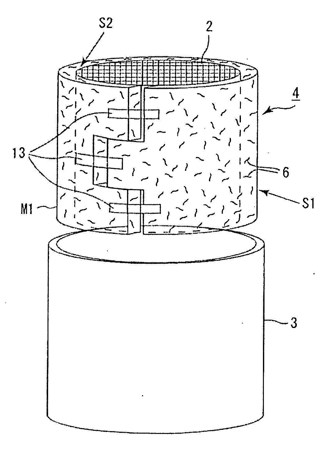
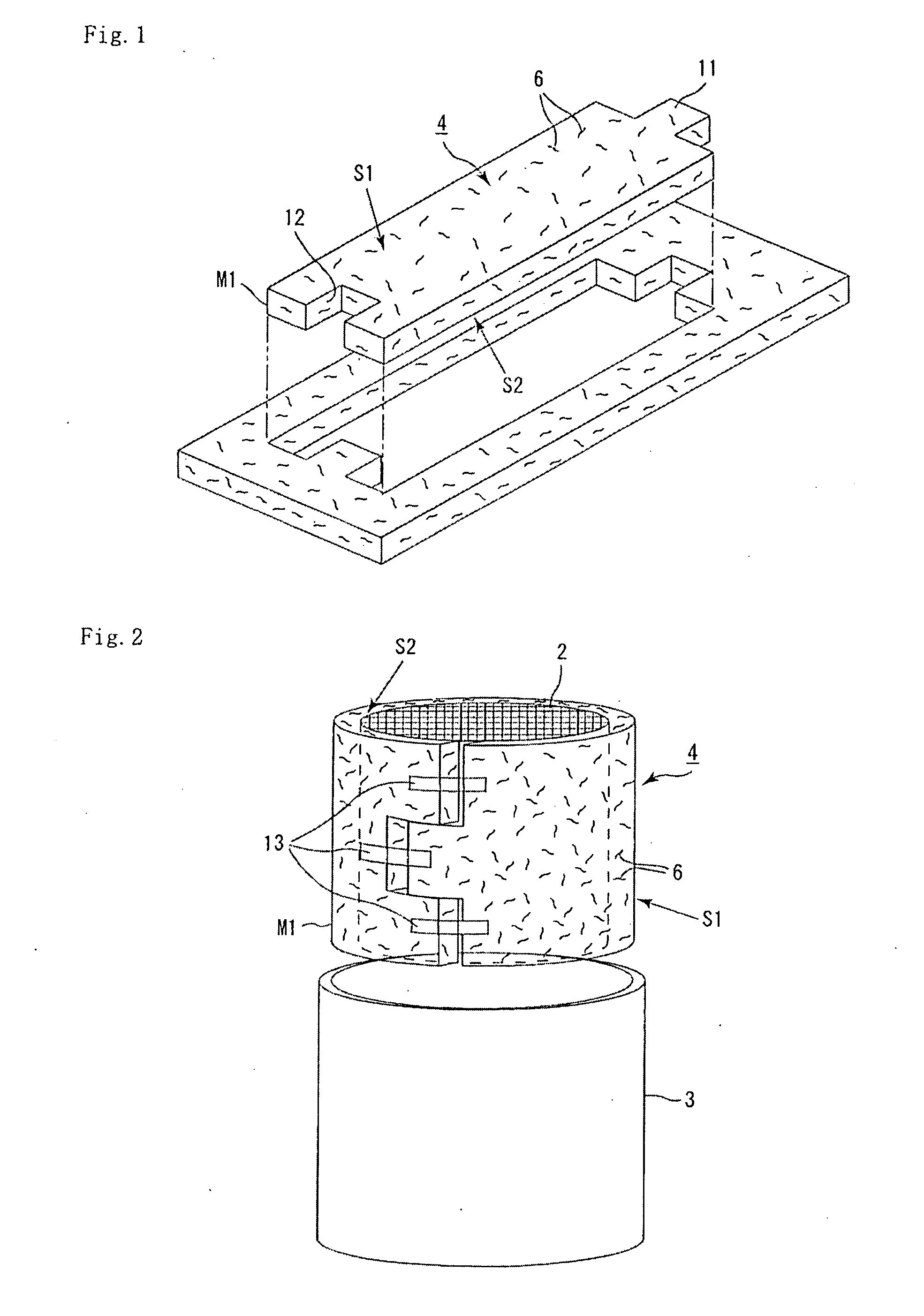
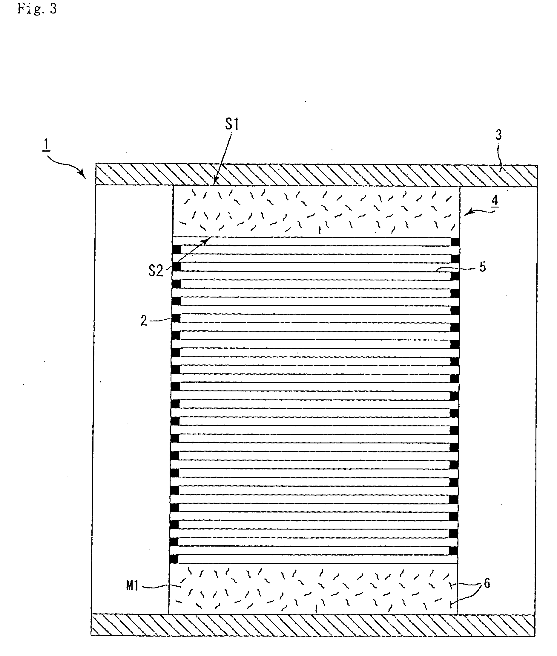
[0415]Referring to FIGS. 1 to 3, as well as FIG. 12, the following description will be given of a catalyst converter used for an automobile exhaust gas purifying device in accordance with the first embodiment according to the fifth group of the present invention in detail.

[0416]This catalyst converter 1 in accordance with the embodiment of the fifth group of the present invention, shown in FIG. 3, is virtually the same as the catalyst converter according to the first group of the present invention, and constituted by a catalyst carrier 2, a metal shell 3 covering the outer circumference of the catalyst carrier 2, and a holding seal material 4 that is placed in a gap between the two members 2 and 3.

[0417]Here, with respect to the catalyst carrier 2 and the metal shell 3, the same members that have been explained in the catalyst converter according to the first group of the present invention may be used; therefore, the description thereof is omitted.

[0418]Moreover, with respect to the...

second embodiment

[0456]The following description will be given of a second embodiment according to the fifth group of the present invention. Here, explanations will be mainly given on points that are different from the first embodiment according to the fifth group of the present invention, and those same parts are indicated by the same reference numerals, and the description thereof is omitted.

[0457]In this case, a holding seal material 4 having the above-mentioned structure is manufactured in the following sequence. First, a spinning process is carried out in the same manner as the first embodiment according to the fifth group of the present invention to provide long fibers of precursor fibers by using a spinning stock solution of the alumina-silica based fibers 6 as a material. Next, a cutting process is carried out so that the long fibers are chopped by a guillotine cutter to form shorter fibers in a certain extent. Then, a molding process is carried out in such a manner that the short fibers are...

example 1

[0531]In example 1, first, a basic water solution of aluminum chloride (23.5% by weight), silica sol (20% by weight, silica particle size 15 nm) and polyvinyl alcohol (10% by weight) that is a fiber-drawing property applying agent were mixed to prepare a spinning stock solution. Next, the resulting spinning stock solution was condensed under vacuum at 50° C. by using an evaporator to prepare a spinning stock solution having a concentration of 38% by weight with a viscosity of 1500 Poise.

[0532]After preparation, the spinning stock solution was continuously discharged into the air through a nozzle (having a complete round shape in its cross-section) of the spinning device, and the precursor fibers thus formed were wound up while being extended.

[0533]Next, after the above-mentioned precursor fibers had been subjected to a heating step (pre-processing) at 250° C. for 30 minutes in an electric furnace that is maintained at normal pressure in a nitrogen atmosphere, these were sintered at ...


PUM

PropertyMeasurementUnit
Percent by massaaaaaaaaaa

Abstract

A manufacturing method by which alumina-silica based fibers excellent in mechanical strength can be readily and securely obtained. The method obtains precursor fibers as a material by using an alumina-silica based fiber spinning stock solution for use in an inorganic salt method. Next, the precursor fibers are heated under an environment which makes it difficult to carry out an oxidizing reaction on the carbon component contained in the precursor fibers. Thus, the precursor fibers are sintered to obtain alumina-silica based fibers.

Description

TECHNICAL FIELD[0001]The present invention relates to an alumina-silica based fiber, a ceramic fiber, a ceramic fiber aggregation, a holding seal material and manufacturing methods thereof, as well as a manufacturing method of alumina fiber aggregation.BACKGROUND ART[0002]Recently, there has been a problem that particulates contained in exhausted gas discharged from combustion engines of vehicles such as buses, trucks, construction machines and the like affect the environment and the human body.[0003]There have been various ceramic filters which allow the exhausted gas to pass through porous ceramic, thereby capturing the particulates in the exhausted gas and purifying the exhausted gas.[0004]As one example of such ceramic filters, there is used a honeycomb filter 30 in which a plurality of porous ceramic members 40 shown in FIG. 16 are bound by means of an adhesive layer 34 to constitute a column-shaped ceramic block 35, and a seal material layer 33 is formed around the column-shap...

Claims


Application Information

Patent Timeline
IPC IPC(8): F16J15/10C04B35/622D01F9/08F01N3/28
CPCB82Y30/00F01N2350/04C04B35/62245C04B35/803C04B2235/422C04B2235/526C04B2235/5264C04B2235/5268C04B2235/5284C04B2235/656C04B2235/6567C04B2235/658C04B2235/80C04B2235/96C04B2235/9661D01D5/04D01D5/253D01F9/10F01N3/2853F01N3/2864F01N2330/06F01N2330/14C04B35/117Y10T428/249928C04B35/80F01N3/28
Inventor TANAHASHI, KAZUTOMODOUSHITA, MASAKAGETAKAHASHI, HIDETOMO
Owner IBIDEN CO LTD
Learn More