
Fuel Cells with Sputter Deposited Pt and Pt Alloy Electrodes

a technology of pt alloy and fuel cells, which is applied in the field of preparing a membrane thin film electrode assembly, can solve the problems of inability to achieve large-scale implementation of pemfcs, performance loss, and extremely time-consuming development of traditional carbon supported alloy nanoparticles

Inactive Publication Date: 2009-04-09
HONDA MOTOR CO LTD
View PDF5 Cites 10 Cited by
  • Summary
  • Abstract
  • Description
  • Claims
  • Application Information

AI Technical Summary

Benefits of technology

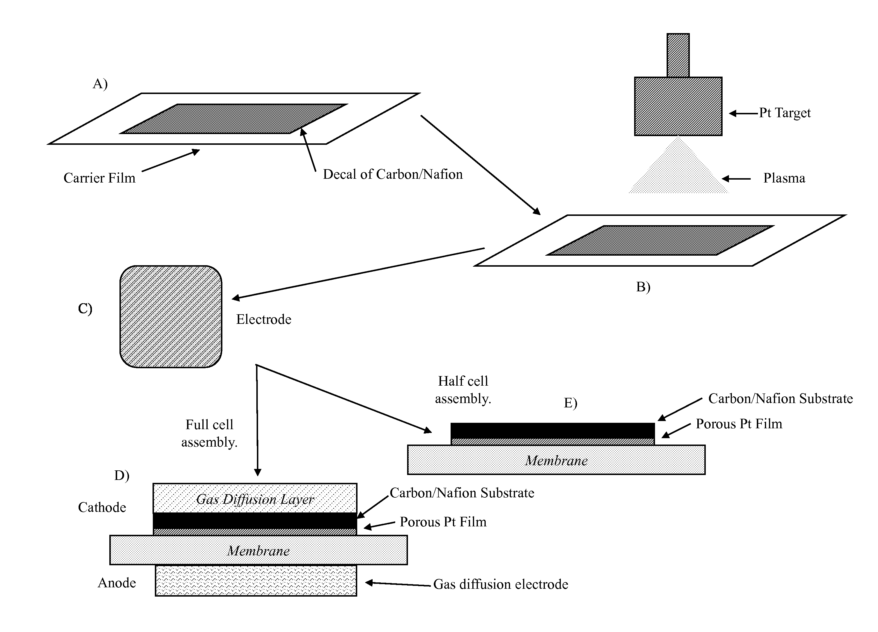
The present patent is about a method of making a membrane thin film electrode assembly by applying a composition onto a carrier film substrate, drying it, and then sputtering a metal or metal alloy onto the dried composition to form a film. This film is then contacted with a polymer electrolyte membrane and hot pressed onto it to form the membrane thin film electrode assembly. The invention also includes a thin film electrocatalyst featuring a decal made up of a support material and an ionomer component, and a thin film of a metal or metal alloy catalyst sputtered onto the composition. Additionally, a membrane electrode assembly is disclosed with a polymer electrolyte membrane having a first face and a second opposing face, with a gas diffusion electrode in contact with the first face and a thin film electrode in contact with the second face, where the thin film electrode can be sandwiched between the second face of the polymer electrolyte membrane and a gas diffusion layer, and the thin film electrode includes a decal made of a support material and an ionomer component, and a thin film of a metal or metal alloy catalyst can be sputtered onto the composition. The technical effects of this patent include improved performance and efficiency of membrane thin film electrode assemblies in fuel cells and other applications.

Problems solved by technology

Currently, large scale implementation of PEMFCs is inhibited due to high material costs and poor long term performance durability.
A significant portion of the cost and durability issues can be attributed to the cathode oxygen reduction catalyst which requires a significantly high loading of platinum (Pt, currently on the order of 0.4 mg / cm2) to overcome the sluggish kinetics of the oxygen reduction reaction at operating temperatures.
Furthermore, studies have shown that Pt nanoparticle coarsening and carbon corrosion in the cathode lead to performance losses with time.
The development of traditional carbon supported alloy nanoparticles is extremely time consuming with different alloy compositions often requiring different fabrication techniques to achieve desired alloy particle size, micro-composition uniformity, and nanoparticle dispersion.

Method used


Image

  • Fuel Cells with Sputter Deposited Pt and Pt Alloy Electrodes
  • Fuel Cells with Sputter Deposited Pt and Pt Alloy Electrodes
  • Fuel Cells with Sputter Deposited Pt and Pt Alloy Electrodes

Examples


examples

Experimental Procedure

1. Preparation of Carbon / Nafion® Decals

[0038]Carbon / Nafion® decal were made by casting carbon / Nafion® ink onto silicone coated Mylar® using a K Paint Applicator (R K Print Coat Instruments Ltd.). The carbon / Nafion® ink was formulated by mixing Vulcan XC72R carbon (Cabot), diluted Nafion® (5 wt %, Aldrich), and 1-propanol (Fisher) to achieve a carbon to Nafion® ratio of 4 to 1 by weight in the dry decal. The decal was dried under ambient conditions and the final thickness was about 10 μm.

2. Deposition of Catalyst Films

[0039]Thin catalyst films were deposited onto the exposed surface of the decals prepared above by using a Kurt J. Lesker CMS-18 physical vapor deposition system at relatively high pressure (75 mTorr Ar) and at low target powers to enhance film porosity. The substrate was rotated to achieve good film thickness uniformity and all depositions were performed at room temperature.

[0040]For pure platinum cathode electrocatalyst films, the platinum target ...


PUM

PropertyMeasurementUnit
pressuresaaaaaaaaaa
pressuresaaaaaaaaaa
pressuresaaaaaaaaaa

Abstract

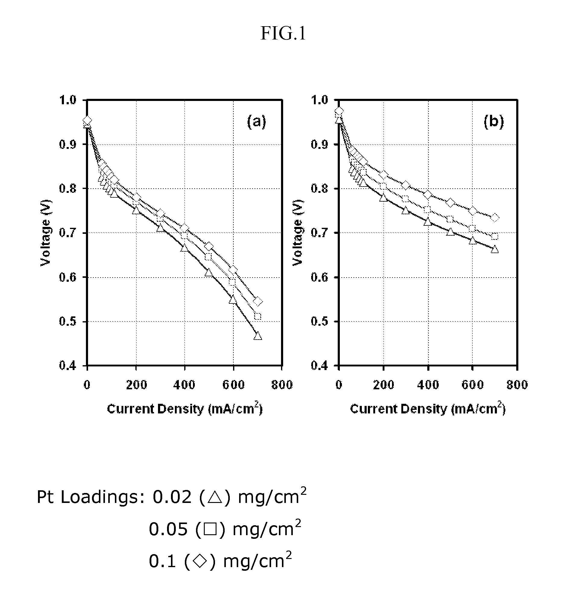
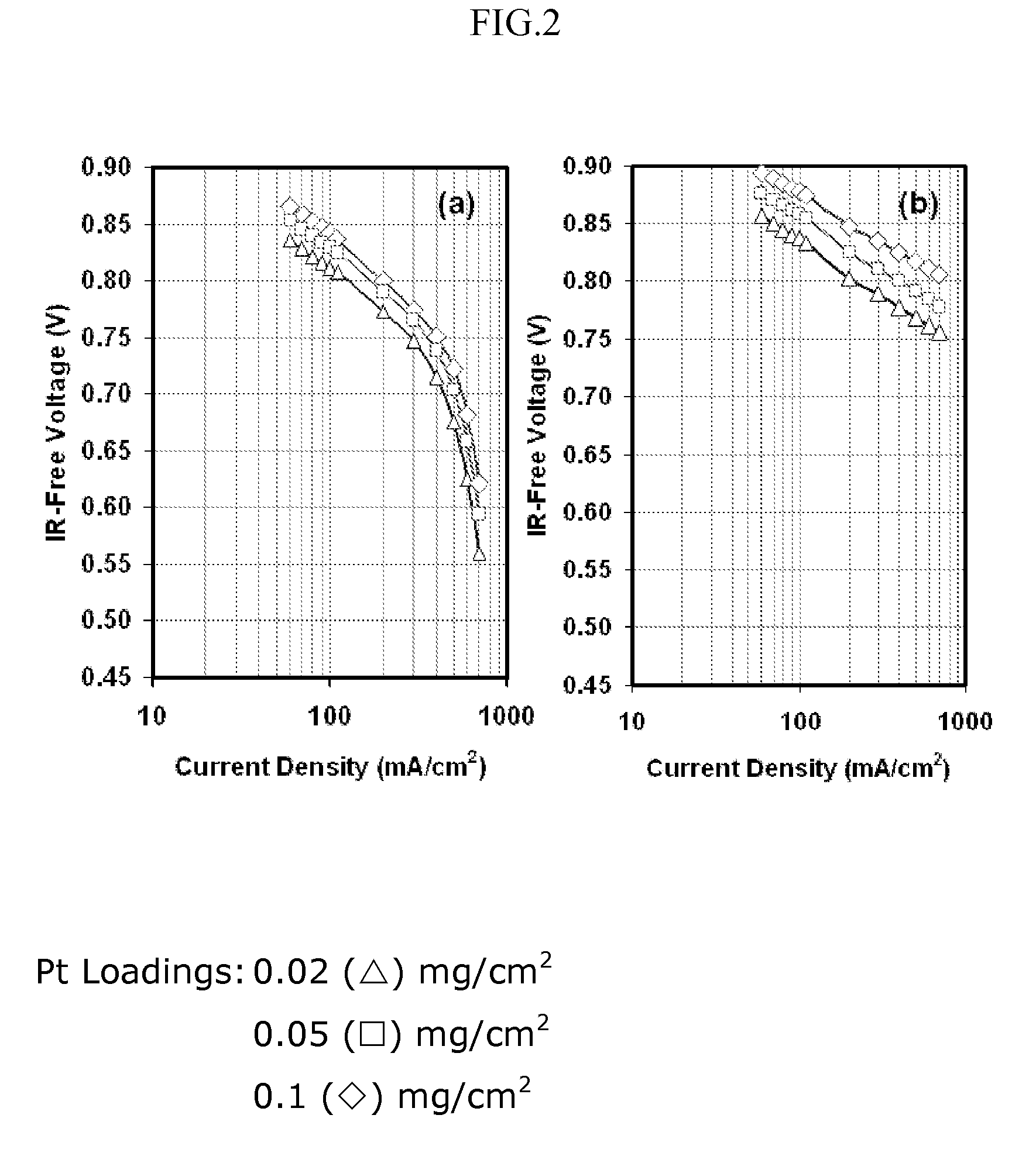
The present application is directed to a fabrication method to reduce Pt loading in fuel cells through the use of thin film electrodes by increasing Pt utilization and the use of more active Pt alloys that can be easily and inexpensively fabricated by sputter deposition. Pt and Pt alloy thin films were sputter deposited onto carbon / Nafion® decals and subsequently hot pressed with the catalyst thin film towards the membrane. The results show improved mass performance and catalyst utilization with Pt thin films and increased mass activities can be achieved with PtCo (76:24 atomic ratio) and PtCr (80:20 atomic ratio) as compared to pure Pt. Mass activity improvements of 14 mV and 8 mV were observed for the PtCo and PtCr alloys with respect to a pure Pt film with similar mass loading under 300 / 350 kPa hydrogen / oxygen operation.

Description

RELATED APPLICATIONS[0001]The present application claims benefit from earlier filed U.S. Provisional Application No. 60 / 977,853, filed Oct. 5, 2007, which is incorporated herein in its entirety by reference for all purposes.BACKGROUND[0002]1. Field of the Invention[0003]The present teachings relate to a method of preparing a membrane thin film electrode assembly. A composition of a support material and an ionomer component is dried on a carrier film, a metal or metal alloy is sputtered onto the dried composition, and a decal with the film of dispersed metal or metal alloy is removed from the carrier film. The decal has a first face of dried composition and a second face of the film of dispersed metal or metal alloy. A polymer electrolyte membrane is provided and the film of dispersed metal or metal alloy on the decal can be contacted to a face of the polymer electrolyte membrane, and then the decal can be hot pressed onto the polymer electrolyte membrane to form the desired membrane...

Claims


Application Information

Patent Timeline
Patent Type & Authority Applications(United States)
IPC IPC(8): H01M8/10
CPCH01M4/8605H01M4/8621H01M4/8657H01M4/8668Y02E60/50H01M4/8871H01M4/8896H01M4/921H01M2008/1095H01M4/8814
Inventor KREIDLER, ERIC ROLLANDHE, TING
Owner HONDA MOTOR CO LTD
Learn More