
Method for manufacturing polishing pad

a polishing pad and manufacturing method technology, applied in the direction of manufacturing tools, grinding devices, chemistry apparatus and processes, etc., can solve the problems of low productivity, large number of production steps, low productivity, etc., and achieve high productivity, high productivity, and manufacture a polishing pad

Inactive Publication Date: 2009-04-09
TOYO TIRE & RUBBER CO LTD
View PDF23 Cites 42 Cited by
  • Summary
  • Abstract
  • Description
  • Claims
  • Application Information

AI Technical Summary

Benefits of technology

[0039]An object of a first invention is to provide a method for manufacturing a polishing pad with a small number of manufacturing processes and high productivity. Another object of the invention is to provide a method for manufacturing a laminated polishing pad with a small number of manufacturing processes, high productivity and no peeling between a polishing layer and a cushion layer.
[0041]A object of a third invention is to provide a method for manufacturing a polishing pad capable of preventing slurry leakage between a polishing region and a light transmitting region with high productivity. Another object of the invention is to provide a method for manufacturing a laminated polishing pad having no peeling between a polishing layer and a cushion layer and capable of preventing slurry leakage between a polishing region and a light transmitting region with high productivity.

Problems solved by technology

Laminate polishing pads are produced by laminating, with an adhesive or double-side tape, a plurality of resin sheets, such as a polishing layer and a cushion layer, obtained by the method described above, and such a method for production of laminate polishing pads has the problems of a large number of production steps and low productivity rate.
However, such conventional groove-forming processes are time-consuming and thus have the problem of low productivity.
Polyurethane foam sheets are excellent in locally planarizing performance but have insufficient cushion performance, and therefore it is difficult to evenly apply a pressure to the entire surface of a wafer from such a polyurethane foam sheet.
However, the conventional laminate polishing pads have a problem in which since they are produced by bonding the polishing layer to the cushion layer with a double-side tape (a pressure-sensitive adhesive layer), a slurry can intrude between the polishing layer and the cushion layer during polishing to reduce the adhesion of the double-side tape so that the polishing layer can be detached from the cushion layer.
When such CMP is conducted, there is a problem of judging the planarity of wafer surface.
In this method, however, the treatment time of a test wafer and the cost for the treatment are wasteful, and a test wafer and a product wafer not subjected to processing are different in polishing results due to a loading effect unique to CMP, and accurate prediction of processing results is difficult without actual processing of the product wafer.
Even in a case where each of the proposed transparent leakage preventive sheets is provided, however, the slurry is leaked out from the interface therebetween up to the lower part of a polishing layer and accumulated on the leakage preventive sheet to thereby cause a problem in optical detection of an endpoint.

Method used


Image

  • Method for manufacturing polishing pad
  • Method for manufacturing polishing pad
  • Method for manufacturing polishing pad

Examples


preparation example 1

[0183]32 parts by weight of toluene diisocyanate (a mixture of 2,4-diisocyanate / 2,6-diisocyanate=80 / 20), 8 parts by weight of 4,4′-dicyclohexylmethane diisocyanate, 54 parts by weight of polytetramethylene glycol (number average molecular weight: 1006), and 6 parts by weight of diethylene glycol were mixed, and stirred and heated at 80° C. for 120 minutes so that an isocyanate-terminated prepolymer (2.1 meq / g in isocyanate equivalent) was prepared. 100 parts by weight of the isocyanate-terminated prepolymer and 3 parts by weight of a silicone surfactant (SH-192, manufactured by Dow Corning Toray Co., Ltd.) were mixed to prepare a mixture A which was controlled to have a temperature of 80° C. In a mixing chamber, 80 parts by weight of the mixture A and 20 parts by weigh of 4,4′-methylenebis(o-chloroaniline) (Iharacuamine MT, manufactured by Ihara Chemical Industry Co., Ltd.) melted at 120° C. were mixed, and at the same time, air was dispersed into the mixture by mechanical stirring ...

preparation example 2

[0186]To a vessel were added 45 parts by weight of POP36 / 28 (polymer polyol, 28 mg KOH / g in hydroxyl value, manufactured by Mitsui Chemicals, Inc.), 40 parts by weight of ED-37A (polyether polyol, 38 mg KOH / g in hydroxyl value, manufactured by Mitsui Chemicals, Inc.), 10 parts by weight of PCL305 (polyester polyol, 305 mg KOH / g in hydroxyl value, manufactured by Daisel Chemical Industries, Ltd.), 5 parts by weight of diethylene glycol, 5.5 parts by weight of a silicone surfactant (SH-192, manufactured by Dow Corning Toray Co., Ltd.), and 0.25 parts by weight of a catalyst (No. 25, manufactured by Kao Corporation) and mixed. The reaction system was vigorously stirred for about 4 minutes with a stirring blade at a rotational speed of 900 rpm such that air bubbles were incorporated into the reaction system. Thereafter, 31.57 parts by weight of Millionate MTL (manufactured by Nippon Polyurethane Industry Co., Ltd.) was added, and the mixture was stirred for about 1 minute to give a cell...

preparation example

[0189]32 parts by weight of toluene diisocyanate (a mixture of 2,4-diisocyanate / 2,6-diisocyanate=80 / 20), 8 parts by weight of 4,4′-dicyclohexylmethane diisocyanate, 54 parts by weight of polytetramethylene glycol (number average molecular weight: 1006), and 6 parts by weight of diethylene glycol were mixed, and stirred and heated at 80° C. for 120 minutes so that an isocyanate-terminated prepolymer (2.1 meq / g in isocyanate equivalent) was prepared. 100 parts by weight of the isocyanate-terminated prepolymer and 3 parts by weight of a silicone surfactant (SH-192, manufactured by Dow Corning Toray Co., Ltd.) were mixed to prepare a mixture A which was controlled to have a temperature of 80° C. In a mixing chamber, 80 parts by weight of the mixture A and 20 parts by weigh of 4,4′-methylenebis(o-chloroaniline) (Iharacuamine MT, manufactured by Ihara Chemical Industry Co., Ltd.) melted at 120° C. were mixed, and at the same time, air was dispersed into the mixture by mechanical stirring ...


PUM

PropertyMeasurementUnit
Viscosityaaaaaaaaaa
Viscosityaaaaaaaaaa
Wavelengthaaaaaaaaaa

Abstract

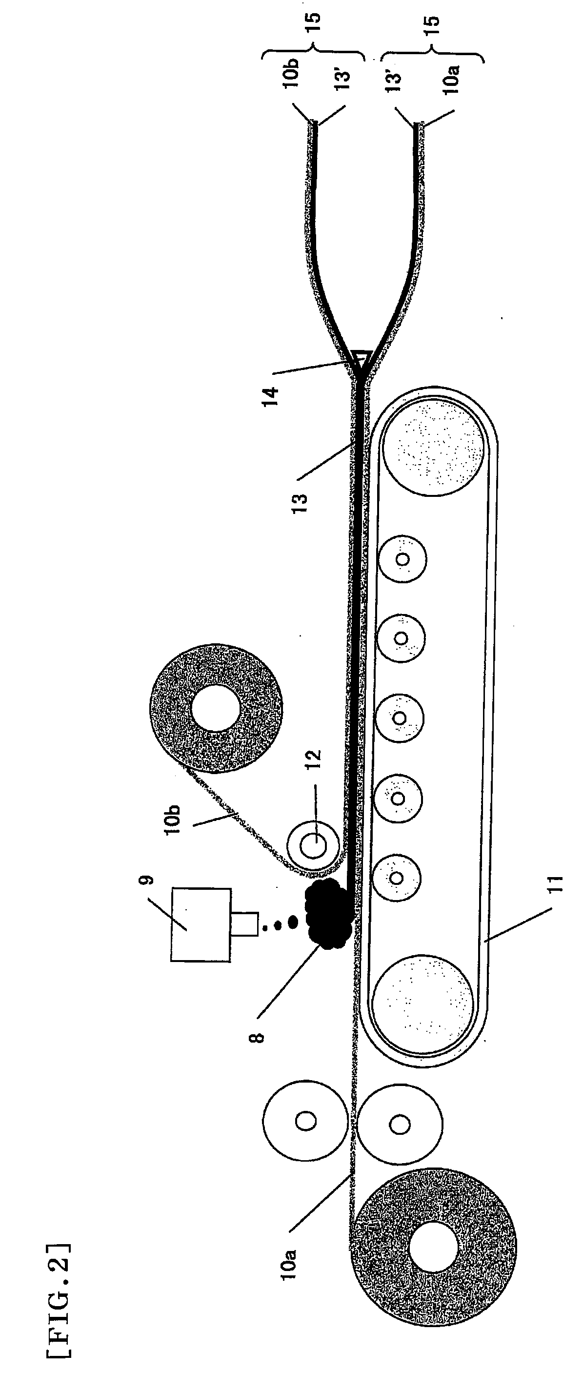
A method for manufacturing a polishing pad, which may be laminated, with a small number of manufacturing steps, high productivity and no peeling between a polishing layer and a cushion layer includes preparing a cell-dispersed urethane composition by a mechanical foaming method; continuously discharging the cell-dispersed urethane composition onto a face material, while feeding the face material; laminating another face material on the cell-dispersed urethane composition; curing the cell-dispersed urethane composition, while controlling its thickness to be uniform, so that a polishing layer including a polyurethane foam is formed; cutting the polishing layer parallel to the face into two pieces so that two long polishing layers each including the polishing layer and the face material are simultaneously formed; and cutting the long polishing layers to produce the polishing pad.

Description

REFERENCE TO RELATED APPLICATIONS[0001]This application is a national stage application under 35 USC 371 of International Application No. PCT / JP2007 / 058493, filed Apr. 19, 2007, which claims the priority of Japanese Patent Application Nos. 2006-115890, filed Apr. 19, 2006, 2006-115897, filed Apr. 19, 2006, 2006-115904, filed Apr. 19, 2006, 2006-115907, filed Apr. 19, 2006, and 2007-0088388, filed Mar. 29, 2007, the contents of all of which prior applications are incorporated herein by reference.FIELD OF THE INVENTION[0002]The present invention relates to a method for production of a (laminated) polishing pad by which the planarizing processing of optical materials such as lenses, reflecting mirrors and the like, silicon wafers, glass substrates for hard disks, aluminum substrates, and materials requiring a high degree of surface planarity such as those in general metal polishing processing can be carried out stably with high polishing efficiency. The (laminated) polishing pad obtain...

Claims


Application Information

Patent Timeline
IPC IPC(8): B24D11/00B24B37/20B24B37/22
CPCB24B37/22B29C44/322B24D18/00B29C44/326B29C44/5654C08J9/30C08J2375/08B24D11/003Y10T156/1052Y10T156/1059B24B37/24B29C44/308B24B37/26B24B37/205B29C44/24B29C44/32B24D3/32C08J5/00H01L21/304
Inventor FUKUDA, TAKESHIWATANABE, TSUGUOHIROSE, JUNJINAKAMURA, KENJIDOURA, MASATO
Owner TOYO TIRE & RUBBER CO LTD
Learn More