Compound and organic el device

a light-emitting device and compound technology, applied in the direction of discharge tube luminescnet screen, other domestic articles, transportation and packaging, etc., can solve the problems of insufficient resolution of emission problems and large number of durability problems of organic light-emitting devices, and achieve high efficiency and high luminance

Inactive Publication Date: 2009-04-16
CANON KK
View PDF9 Cites 10 Cited by
  • Summary
  • Abstract
  • Description
  • Claims
  • Application Information

AI Technical Summary

Benefits of technology

[0009]The compound of the present invention can be suitably utilized in a light-emitting device. In addition, the light-emitting device of the present invention using such compound in its light-emitting layer is an excellent device capable of not only emitting l

Problems solved by technology

In addition, the organic light-emitting device still involves a large number of problems in terms of durability such as a change with elapse of time due to long-term u

Method used


Image

  • Compound and organic el device
  • Compound and organic el device
  • Compound and organic el device

Examples


example 1

Synthesis of Exemplified Compound No. F-28

[0051]

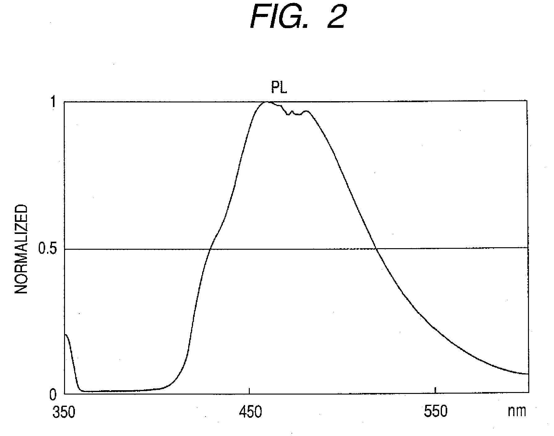
[0052]360 mg (1 mmole) of Compound 1-1, 450 mg (3 mmole) of Compound 1-2 (manufactured by SIGMA-ALDRICH), 0.1 g of Pd(PPh3)4, 10 ml of toluene, 5 ml of ethanol, and 10 ml of a 2M aqueous solution of sodium carbonate were charged into a 100-ml egg plant flask, and the mixture was stirred in a stream of nitrogen at 80° C. for 8 hours. After the completion of the reaction, the crystal was separated by filtration, and was washed with water and ethanol. After having been subjected to hot filtration with toluene, the resultant crystal was recrystallized with toluene / heptane and dried in a vacuum at 120° C., whereby 356 mg of Exemplified Compound No. F-28 were obtained (yield: 87%).

[0053]FIG. 2 shows the graph of the light-emitting characteristics of the compound in toluene.

example 2

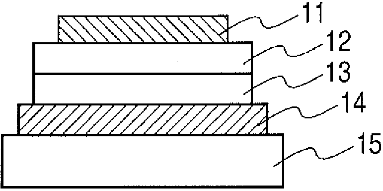
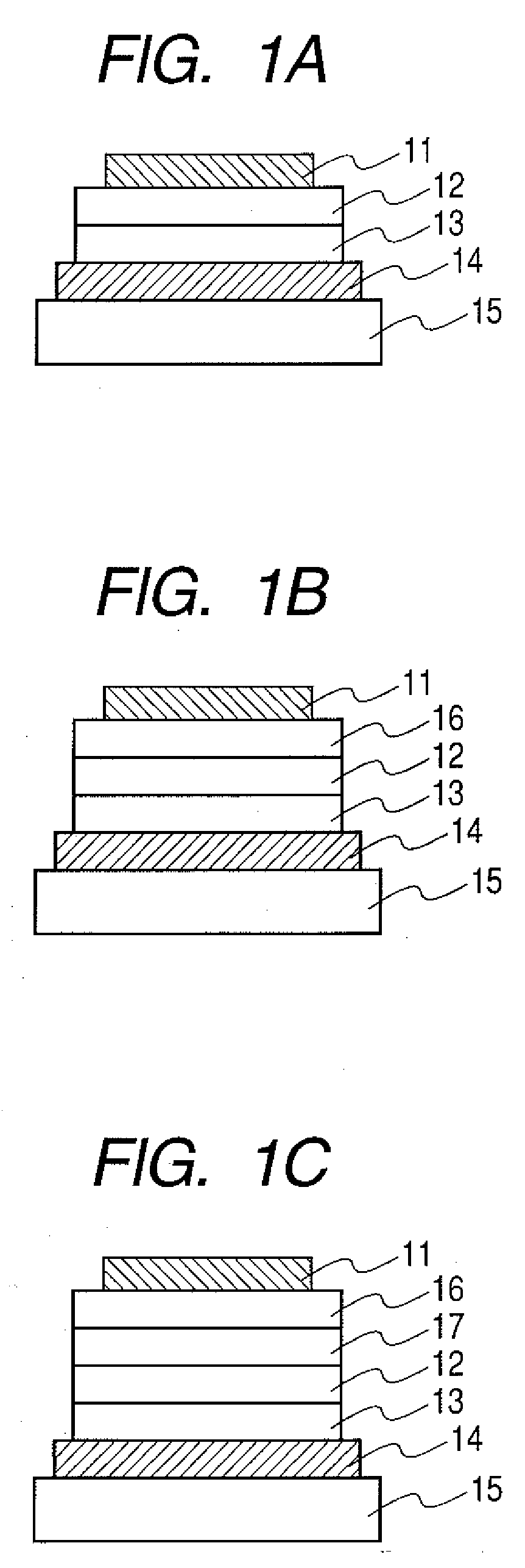
[0054]In this example, a device having such device constitution including three organic layers as shown in FIG. 1B was used. ITO was patterned onto a glass substrate to form a pattern having a thickness of 100 nm. The following organic layers and electrode layers were continuously formed on the resultant ITO substrate by vacuum vapor deposition using resistance heating in a vacuum chamber at a pressure of 10−5 Pa so that an opposing electrode area was 3 mm2.

Device A:

[0055]Hole transport layer (20 nm): Compound A

[0056]Light-emitting layer (25 nm): Exemplified Compound No. F-28 (weight ratio 5%):Compound B

[0057]Electron transport layer (40 nm): Bphen

[0058]Metal electrode layer 1 (1 nm): KF

[0059]Metal electrode layer 2 (100 nm): Al

[0060]The current-voltage characteristics of the EL device were measured with a microammeter 4140B manufactured by Hewlett-Packard Company, and the emission luminance of the device was measured with a BM7 manufactured by TOPCON CORPORATION. As a result, the o...

example 3

Synthesis of Exemplified Compound No. F-

[0061]

[0062]984 mg (4 mmole) of Compound 3-1, 1,420 mg (4 mmole) of Compound 3-2, 0.1 g of Pd(PPh3)4, 20 ml of toluene, 10 ml of ethanol, and 20 ml of a 2-M aqueous solution of sodium carbonate were charged into a 200-ml egg plant flask, and the mixture was stirred in a stream of nitrogen at 80° C. for 8 hours. After the completion of the reaction, the crystal was separated by filtration, and was washed with water and ethanol. After having been subjected to hot filtration with toluene, the resultant crystal was recrystallized with toluene / heptane and dried in a vacuum at 120° C., whereby 900 mg of Exemplified Compound No. F-11 were obtained (yield: 72%).

[0063]FIG. 3 shows the graph of the light-emitting characteristic of the compound in toluene.

[0064]Matrix-assisted laser desorption / ionization time-of-flight mass spectrometry (MALDI-TOF MS) confirmed that the compound had an M+ of 430.1.

[0065]A device was produced in the same manner as in Exam...


PUM

PropertyMeasurementUnit
Structureaaaaaaaaaa

Abstract

The present invention provides a high-performance organic EL device and a novel compound used for the device. The novel compound of the present invention is a fluoranthene compound having a specific structure. The organic EL device of the present invention is an organic EL device comprising: an anode; a cathode; and an organic compound layer interposed between the anode and the cathode, wherein the organic compound layer has the fluoranthene compound.

Description

TECHNICAL FIELD[0001]The present invention relates to a novel organic compound and a light-emitting device having the compound.BACKGROUND ART[0002]An organic light-emitting device has a constitution in which a thin film containing a fluorescent organic compound or a phosphorescent organic compound is interposed between an anode and a cathode. Electrons and holes are injected from the respective electrodes so that excitons of the fluorescent compound or of the phosphorescent compound are generated. The organic light-emitting device utilizes light to be radiated upon return of the excitons to a ground state.[0003]A benzofluoranthene compound has been researched (Japanese Patent Application Laid-Open Nos. H10-189247, 2005-235787, 2000-7587, 2000-7594, and 2005-68087).DISCLOSURE OF THE INVENTION[0004]However, at present, an optical output with additionally high luminance or additionally high conversion efficiency has been needed. In addition, the organic light-emitting device still invo...

Claims


Application Information

Patent Timeline
IPC IPC(8): H01J1/63C07C25/13C07C43/205
CPCC07C13/66C07C2103/40C09K11/06C09K2211/1007Y10T428/265H01L51/0054H01L51/5012H05B33/14Y10S428/917C09K2211/1011C07C2603/40Y10T428/31504H10K85/622H10K50/11C07C4/26C07C15/14C07C15/16C07C211/14H10K50/12H10K50/81
Inventor KAMATANI, JUNOKADA, SHINJIROTAKIGUCHI, TAKAOSAITOH, AKIHITOOKINAKA, KEIJIIGAWA, SATOSHIYAMADA, NAOKIHASHIMOTO, MASASHI
Owner CANON KK
Why Eureka
Try Eureka