Cantilever for near field optical microscopes, plasmon enhanced fluorescence microscope employing the cantilever, and fluorescence detecting method

Inactive Publication Date: 2009-04-23
FUJIFILM CORP
View PDF4 Cites 7 Cited by
  • Summary
  • Abstract
  • Description
  • Claims
  • Application Information

AI Technical Summary

Benefits of technology

[0010]The present invention has been developed in view of the foregoing circumstances. It is an object of the present invention to provide a cantilever for near field optical microscopes which is capable of effectively utilizing the electric field enhancing effect of plasmon and securing the quantitative properties of fluorescent signals by suppressing metallic light loss. It is another object of the present invention to provide a plasmon enhanced fluorescence microscope and a plasmon enhanced fluorescence detecting method that employ the cantilever.
[0028]the near field light being enhanced by the electric field enhancing effect of the local plasmon.
[0036](B) causing the leading end of the probe of the cantilever for near field optical microscopes defined in claim 1 to approach the detection section, and causing enhanced near field light to be generated at the leading end of the probe;
[0044]In the cantilever for near field optical microscopes, the plasmon enhanced fluorescence microscope, and the plasmon enhanced fluorescence detecting method of the present invention, the metal portion of the probe is coated by the thin dielectric film. Thereby, the distance between the metal portion and the fluorescent labels (fluorescent materials) can be controlled, and metallic light loss of the fluorescence emitted by the fluorescent labels can be suppressed. Accordingly, the electric field enhancing effect of plasmon can be effectively utilized and the quantitative properties of fluorescent signals can be secured.
[0046]Further, measurement can be performed with extremely small amounts of biological samples, which are generally known to be expensive. Therefore, large cost reductions are possible.

Problems solved by technology

Therefore, although Raman spectroscopy is effective for qualitative analysis, expectations cannot be held regarding the quantitative properties thereof.
Further, Raman spectroscopy apparatuses are generally large, expensive, and have poor operability.
However, metallic light loss caused by metal probes is a problem.
Thereby, the energy which is to be utilized to emit fluorescence is reduced, the fluorescence quantum yield of the fluorescent substances decreases, and quantitative properties of fluorescent signals cannot be secured.

Method used


Image

  • Cantilever for near field optical microscopes, plasmon enhanced fluorescence microscope employing the cantilever, and fluorescence detecting method
  • Cantilever for near field optical microscopes, plasmon enhanced fluorescence microscope employing the cantilever, and fluorescence detecting method
  • Cantilever for near field optical microscopes, plasmon enhanced fluorescence microscope employing the cantilever, and fluorescence detecting method

Examples


first embodiment

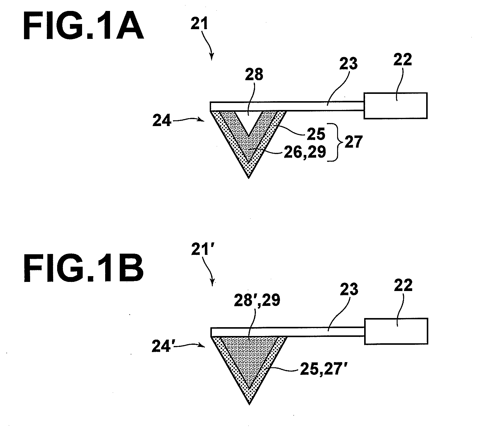
[0053]FIG. 1A is a schematic sectional view of a cantilever 21 for near field optical microscopes according to a first embodiment of the present invention, taken along the longitudinal axis of a lever portion 23 of the cantilever. As illustrated in FIG. 1A, the cantilever 21 is equipped with a support portion 22, the lever portion 23, and a conically shaped probe 24, which is formed in the vicinity of the free end of the lever portion 23. A bulk portion 28 of the probe 24 is formed by a non metallic material, and a thin film portion 27 of the probe 24 is constituted by a thin dielectric film 25 as its outermost layer, and a thin metal film 26.

[0054]Inorganic oxides or polymer films may be employed as the thin dielectric film 25. It is desirable for the material of the thin dielectric film 25 to be selected from a group consisting of: silicon oxide film; polystyrene; PMMA (polymethyl methacrylate); polycarbonate; and cycloolefin. Silicon oxide film (SiO2) is particularly preferred fr...

second embodiment

[0057]FIG. 1B is a schematic sectional view of a cantilever 21′ for near field optical microscopes according to a second embodiment of the present invention. As illustrated in FIG. 1B, the cantilever 21′ is equipped with a support portion 22, a lever portion 23, and a conically shaped probe 24′, which is formed in the vicinity of the free end of the lever portion 23. A bulk portion 28′ of the probe 24′ is formed by a metallic material, and a thin film portion 27′ of the probe 24′ is constituted by a thin dielectric film 25.

[0058]In the second embodiment, the probe 24′ functions as the metal portion 29 at which local plasmon is generated. For this reason, it is desirable for the bulk portion 28′ to be formed by Au, Ag, Pt, or the like, from the viewpoint of conditions for generating local plasmon.

[0059]The thin dielectric film 25 is the same as that of the first embodiment.

[0060]The cantilever 21′ of the second embodiment can obtain the same advantageous effects as those obtained by ...

third embodiment

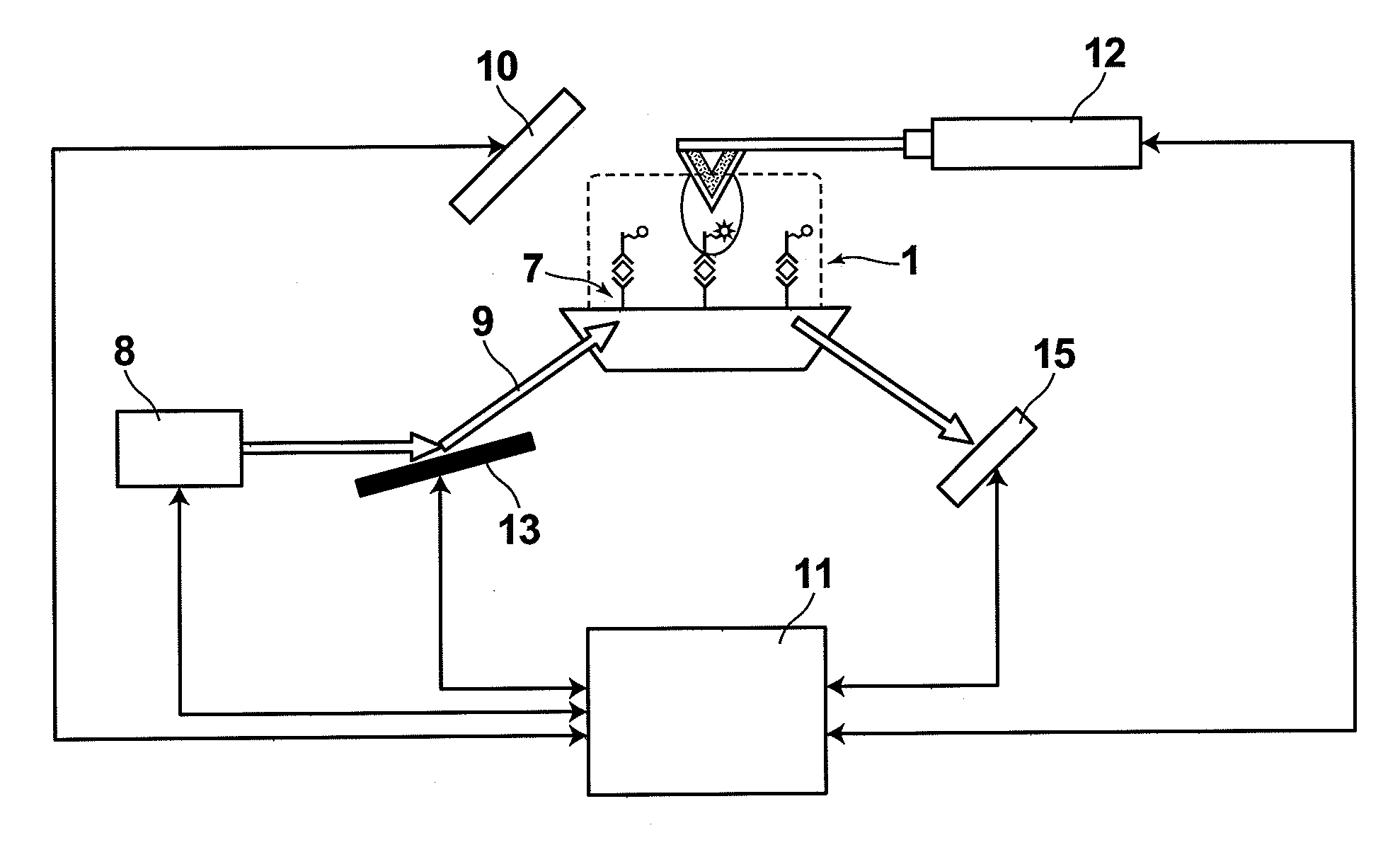
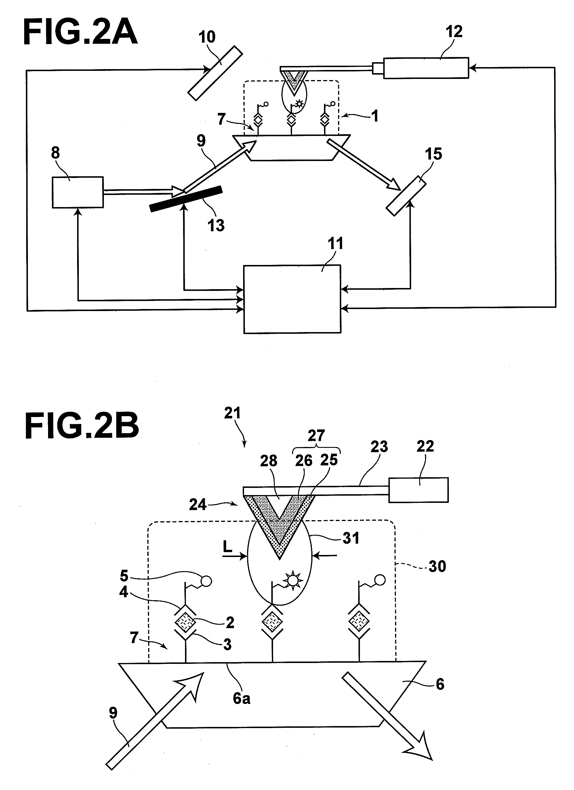
[0061]A plasmon enhanced fluorescence microscope according to a third embodiment of the present invention will be described with reference to FIG. 2A and FIG. 2B.

[0062]FIG. 2A is a schematic diagram that illustrates the construction of the plasmon enhanced fluorescence microscope of the third embodiment. FIG. 2B is a magnified sectional view that schematically illustrates a detection section 7 of the plasmon enhanced fluorescence microscope of FIG. 2A.

[0063]A case is considered in which this plasmon enhanced fluorescence microscope is employed to detect avidin 2 as a detection target substance included in a sample 1. The plasmon enhanced fluorescence microscope is equipped with: a dielectric prism substrate 6 which has the detection section 7; surface modifications (not shown) which are provided on the detection section 7; primary antibodies 3, which are immobilized on the surface modifications, that specifically bind with avidin 2; the cantilever 21 for near field optical microscop...


PUM


Abstract

A cantilever for near field optical microscopes is equipped with a probe in the vicinity of a free end thereof. The probe includes a thin film portion constituted by at least one layer of thin film that serves as the surface of the probe, and an inner bulk portion which is covered by the thin film portion. The outermost layer of the thin film portion is a thin dielectric film, and a metal portion is provided toward the interior of the probe from the thin dielectric film.

Description

BACKGROUND OF THE INVENTION[0001]1. Field of the Invention[0002]The present invention is related to a cantilever for near field optical microscopes. The present invention is also related to a fluorescence microscope and a fluorescence detecting method that employ the cantilever. More specifically, the present invention is related to a plasmon enhanced fluorescence microscope and a plasmon enhanced fluorescence detecting method that utilize plasmon enhancement.[0003]2. Description of the Related Art[0004]Near field optical microscopes are optical microscopes that observe, analyze, and process samples with probes in which photons are sealed within regions less than or equal to diffraction limits. Illuminated light is focused into a region of less than or equal to several tens of nanometers by near field probes, and light which is scattered by and which is transmitted through substances present within the region or fluorescence emitted by the substances are detected through a spectrosc...

Claims


Application Information

Patent Timeline
IPC IPC(8): G01N23/00G01B5/28G01J1/58G01N21/64G01Q60/22
CPCB82Y20/00B82Y35/00G01Q60/22G01Q60/20G01N21/648
Inventor OHTSUKA, HISASHI
Owner FUJIFILM CORP
Why Eureka
Try Eureka