Cluster film formation system and film formation method, and cluster formation system and formation method

a cluster film and film technology, applied in the field of cluster film formation system and film formation method, to achieve the effect of mass production of clusters, improving cluster manufacturing capability, and uniform size of nano-clusters

Inactive Publication Date: 2009-05-07
NAT INST OF ADVANCED IND SCI & TECH
View PDF8 Cites 15 Cited by
  • Summary
  • Abstract
  • Description
  • Claims
  • Application Information

AI Technical Summary

Benefits of technology

[0050]This configuration, similarly to claim 8, not limited to the cluster film formation system according to claim 1, provides the cluster formation method, and allows for economical cluster formation by widely improving a cluster manufacturing capability by the conventional method.
[0051]The configurations of the present invention, to enhance a film manufacturing rate of nano-clusters uniform in size, provide effective, mass production of clusters by optimally setting the increased beam energy of the laser beams, the beam size for target irradiation, and the dimensions of the cluster formation container, and further solve a number of the problems caused by the augmentation of the laser beam strength to increase the amount of evaporation of the material vapor, and address rapid shrinkage of the target material at this time to allow for constant cluster formation. Consequently, the cluster film formation techniques and the systems thereof can be provided that allow for economical efficiency required for cluster film formation.

Problems solved by technology

In this case, it is necessary to efficiently generate a shock wave corresponding to the increase in the amount of vapor, and there is an issue that the generated shock wave is reflected by a wall of the cluster formation container to form a region for effectively confining the vapor.
Further, there are issues how to address a number of problems caused by the augmentation of the laser beam strength, that is, treatment for heat generation caused by introducing laser beams in a cluster film manufacturing system, measurement of strength distribution of the beams on a target irradiation surface, and prevention from shrinkage of the target surface caused by evaporation.

Method used


Image

  • Cluster film formation system and film formation method, and cluster formation system and formation method
  • Cluster film formation system and film formation method, and cluster formation system and formation method
  • Cluster film formation system and film formation method, and cluster formation system and formation method

Examples


first embodiment

[0094]First, referring to FIG. 1, a first embodiment of the present invention will be described.

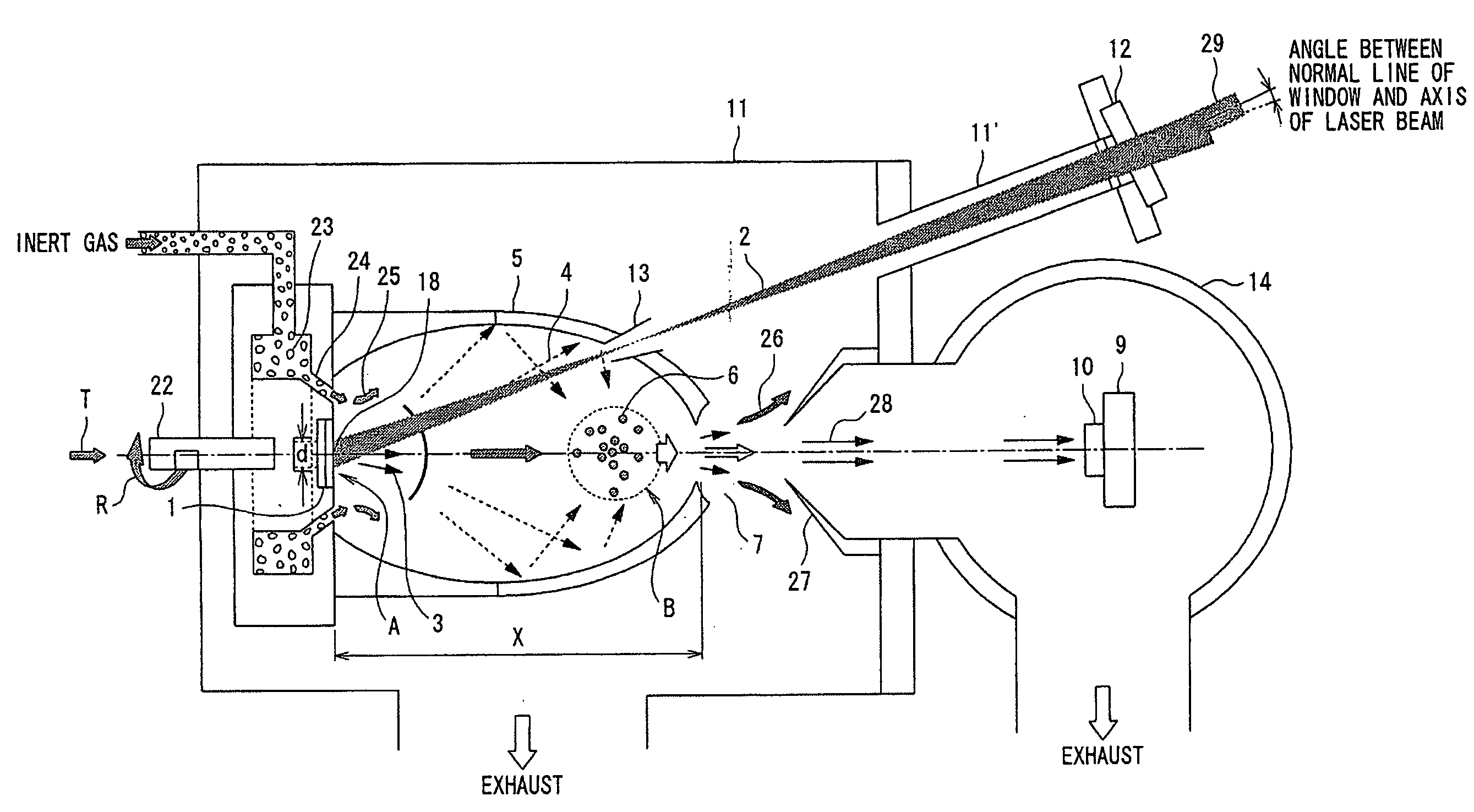
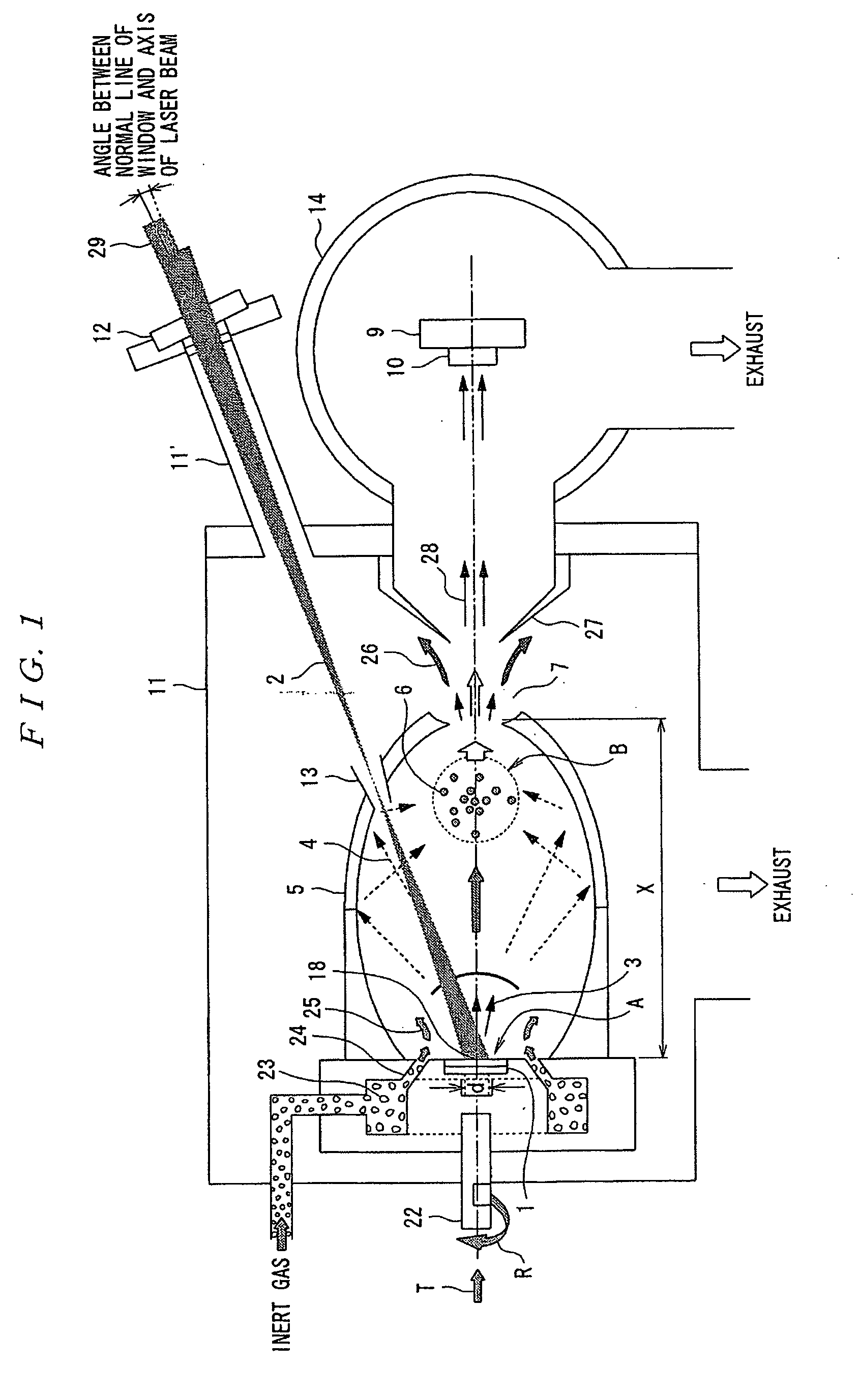
[0095]FIG. 1 is a schematic diagram showing an overall configuration of a cluster film formation system according to the first embodiment of the present invention.

[0096]This cluster film formation system includes a cluster formation container 5 for forming groups of clusters 6, a laser beam source for providing laser beams 2 (not shown), and a cluster film formation container 14 in which a substrate 9 having the groups of clusters 6 sprayed deposited thereon is placed.

[0097]The cluster formation container 5 has target material 1 providing raw material of cluster placed therein, and forms groups of clusters while introducing an inert gas. Further, the cluster formation container 5 has an outflow window 7 for making the groups of clusters flow out, and an entrance window 13 for introducing the laser beams 2, provided at a position different from that of the outflow window 7, and the entranc...

second embodiment

[0112]Next, referring to FIG. 5, a cluster film formation system according to a second embodiment of the present invention will be described.

[0113]FIG. 5 is a schematic diagram for illustrating a configuration of a laser beam introducing portion.

[0114]The second embodiment proposes a structure of a window provided in an external container 11 to introduce intensive laser beams 2 from the outside of the external container 11 surrounding the outside of a cluster formation container 5 as shown in FIG. 5. The external container 11 is brought into a vacuum or quasi-vacuum environment, and the window maintains airtightness with an optically transparent material 12. Then, to pass through the intensive laser beams 2, first, the window is positioned to lower energy density of the beams passing through the window by providing a predetermined distance from a position of a bore 13 of a window in the cluster formation container 5, the bore 13 of the window being positioned at a focal point of the...

third embodiment

[0117]Next, referring to FIG. 6, a cluster film formation system according to a third embodiment of the present invention will be described.

[0118]FIG. 6 is a schematic diagram illustrating a mounting angle of the sealing window 12 composed of the optically transparent material provided in the extension 11′ of the external container 11 for introducing the laser beams 2 shown in FIG. 5.

[0119]The third embodiment, as shown in FIG. 6, relates to a structure of the sealing window 12 (optically transparent material) in the extension 11′ formed by extending the external container 11 for introducing the intensive laser beams 2 from the outside of the external container 11 surrounding the outside of the cluster formation container 5. That is, the structure is characterized in that a perpendicular M to the surface of the sealing window 12 (optically transparent material) is shifted from an optical axis N of the laser beams 2 by a predetermined angle L when the sealing window 12 (optically tra...


PUM

PropertyMeasurementUnit
energyaaaaaaaaaa
energy strengthaaaaaaaaaa
transparentaaaaaaaaaa

Abstract

The invention provides a cluster film formation system in which, in a cluster formation container 5, target 1 is irradiated with laser beams 2 to generate material vapor, which generates a shock wave 4 of an inert gas, and the shock wave 4 is reflected by a wall of the cluster formation container 5 to confine the material vapor having progressed in a particular region, and atoms or molecules of the material vapor and the inert gas collide with each other mutually to form groups of clusters, which are made to flow out through an outflow window 7, and sprayed deposited on a substrate 9 to form a cluster film 10. Corresponding to augmentation of energy strength of the laser beams 2, a cross section area of the laser beams 2 on the surface of the target is made large, thereby an increase in the amount of generation of the material vapor and efficient generation of the shock wave of the inert gas both are realized, and at the same time, the cluster formation container is enlarged so that the reflected wave of the shock wave meets conditions for confining the material vapor.

Description

TECHNICAL FIELD[0001]The present invention relates to a cluster film formation system and a film formation method, and a cluster formation system and a formation method by laser ablation used for depositing clusters on a substrate to form a film-like aggregate of clusters.BACKGROUND ART[0002]In these years, it has been required to control characteristics of a microstructure equal to or smaller than 10 nm. It is because miniaturization is expected to cause material properties to change, providing application to many fields such as nanoelectronics, optical electronics, and biotechnologies. For a general film formation technique of material, Plasma Chemical Vapor Deposition (CVD), Ion Sputtering CVD, and Laser CVD have been conventionally used, and widely put to practical use in the industrial world because of their characteristic of efficient film formation capability on a large area substrate (Patent Document 1). However, as film formation techniques including control of a nanoscale ...

Claims


Application Information

Patent Timeline
Patent Type & Authority Applications(United States)
IPC IPC(8): A61N5/00
CPCC23C14/28C23C14/228
Inventor IWATA, YASUSHITAKIYA, TOSHIO
Owner NAT INST OF ADVANCED IND SCI & TECH
Why Eureka
Try Eureka