
Light-emitting material

a technology of light-emitting materials and materials, applied in the field of light-emitting materials, can solve the problems of slow and inefficient luminescence, waste of energy in the triplet state, and low efficiency of el, and achieve the effect of improving chemical and thermal stability, without any risk of decomposition nor degradation

Inactive Publication Date: 2009-05-07
SOLVAY SA
View PDF7 Cites 4 Cited by
  • Summary
  • Abstract
  • Description
  • Claims
  • Application Information

AI Technical Summary

Benefits of technology

[0036]Complexes complying with formula (XII) here above, thanks to the substitution of one or more hydrogen atoms with fluorine atoms or alkoxy groups advantageously exhibit improved chemical and thermal stability, which enable handling and treating them in further processing technologies without any risk of decomposition nor degradation.

Problems solved by technology

On the contrary, if the symmetry of an exciton is different from the one of the ground state, then the radiative relaxation of the exciton is disallowed and luminescence will be slow and inefficient.
Because the ground state is usually anti-symmetric, decay from a triplet breaks symmetry: the process is thus disallowed and efficiency of EL is very low.
Thus the energy contained in the triplet states is mostly wasted.
However, only a few organic materials have been identified which show efficient room temperature phosphorescence from triplets.
However, since the foregoing light-emitting materials of the prior art do not display pure colours, i.e. their emission bands, generally limited to green, are not centered near selected spectral regions, which correspond to one of the three primary colours, red, green and blue, the range within they can be applied as OLED active compound is narrow.
Triple emissive blue has been recognized in the art as difficult to attain due to the high energy of the emissive state.

Method used


Image

  • Light-emitting material
  • Light-emitting material
  • Light-emitting material

Examples


Embodiment Construction

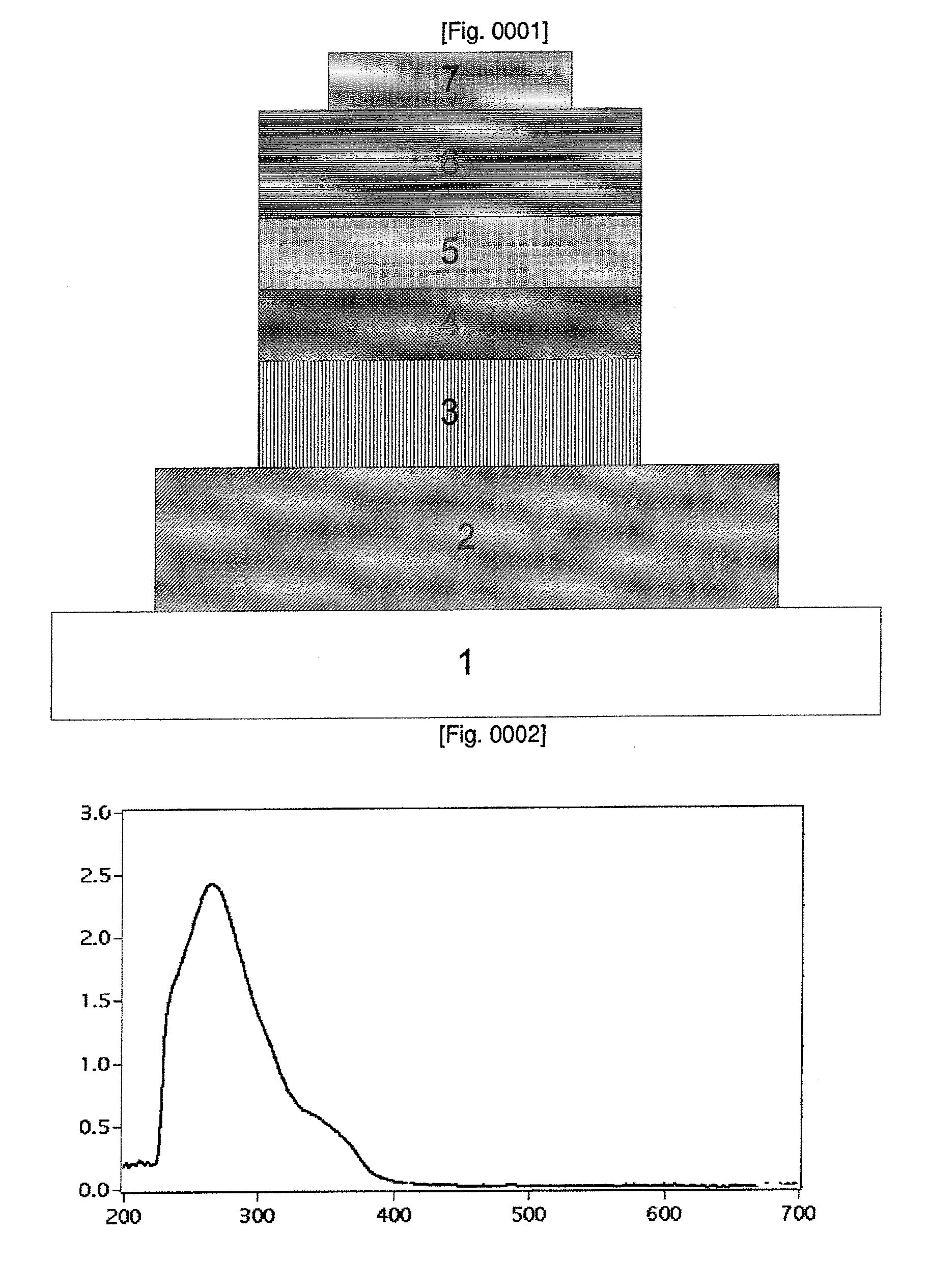
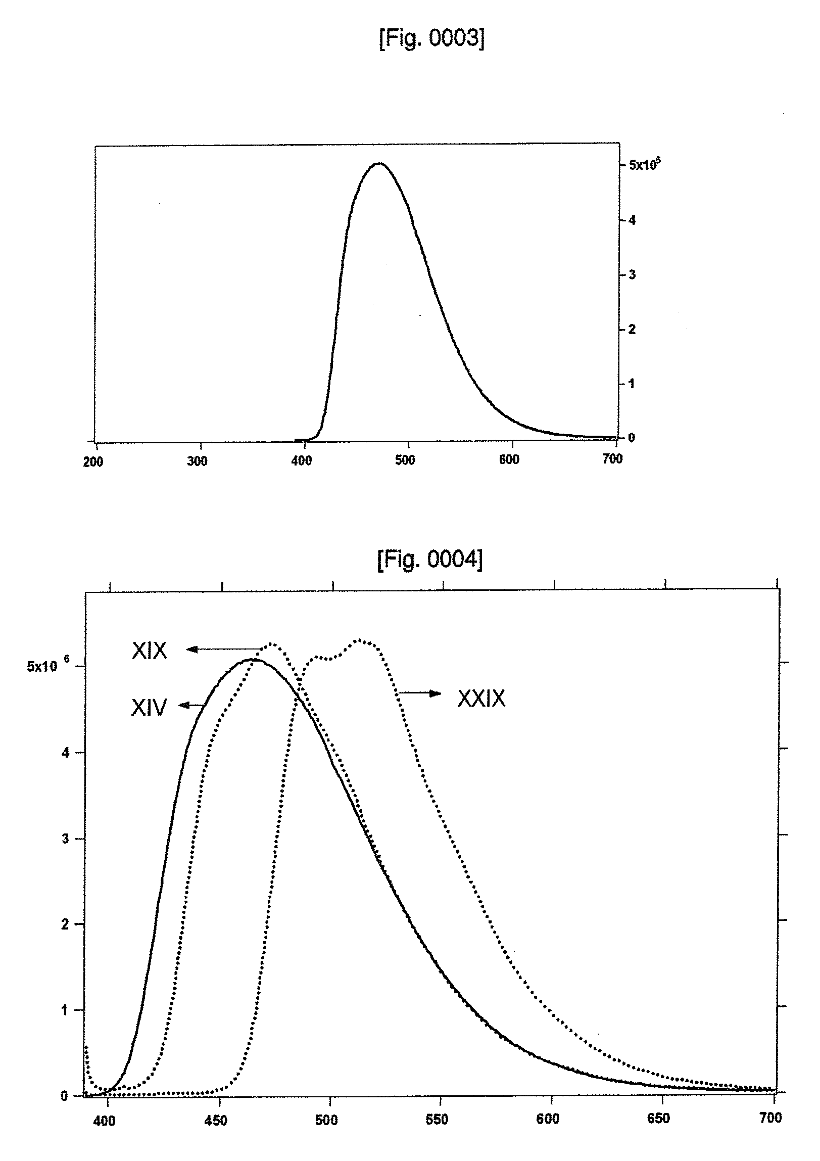
[0069]UV-VIS Measurements: UV-VIS spectra were recorded in a 1 cm path length quartz cell on a Cary 5 spectrophotometer. Emission spectra were recorded on a Spex Fluorolog 112 using a 90° optical geometry. The emitted light was detected with a Hamamatsu R2658 photomultiplier operated in single photon counting mode. The emission spectra were photometrically corrected using a NBS calibrated 200 W tungsten lamp as reference source. The absorption and the emission spectra were obtained by dissolving the solids in dichloromethane solvent and the concentrations were in the range of 5×10⁻⁶ to 1×10⁻⁵ M. All the emission spectra were obtained by exciting at 380 nm and the typical concentrations were 1×10⁵ M.

Synthesis of 2-iodo-4-dimethylaminopyridine

[0070]BF3.Et2O (8.4 g 59 mmol) was added dropwise to a solution of 4-dimethylaminopyridine (6 g 49 mmol) in dry THF (250 ml) at 0° C. The resulting mixture was stirred 1 hour at 0° C. under nitrogen. Temperature was cooled down to −78° C. and BuL...


PUM

PropertyMeasurementUnit
atomic numberaaaaaaaaaa
metallicaaaaaaaaaa
electric energyaaaaaaaaaa

Abstract

This invention pertains to light emitting materials comprising novel ortho-metalated transition metal complexes [ĈN]2M(T)(L), comprising chelate dialkylamino-substituted ĈN ligands, monodentate neutral ligand (L) having sp2 hybridized N atom and a monodentate anionic ligand (T) chosen among CN−, CNO−, CNS−. It has been surprisingly found that when the metal has bound thereto in addition to substituted orthometalated ligands, both an anion chosen among cyanide, thiocyanate, cyanate, possessing strong C donor and π acceptor properties, and a monodentate neutral ligand L, as above defined, said ligands advantageously participate in the emission process, significantly shifting emission towards higher energies (blue-shift) and enabling appreciable improvement of the emission efficiency of complexes [ĈN]2M(T)(L).Still objects of the invention are the use of said light emitting materials and organic light emitting device comprising said light emitting material.

Description

TECHNICAL FIELD[0001]This invention relates to a light-emitting material, to the use of said material and to light-emitting device capable of converting electric energy to light.BACKGROUND ART[0002]Today, various display devices have been under active study and development, in particular those based on electroluminescence (EL) from organic materials.[0003]In the contrast to photoluminescence, i.e. the light emission from an active material as a consequence of optical absorption and relaxation by radiative decay of an excited state, electroluminescence (EL) is a non-thermal generation of light resulting from the application of an electric field to a substrate. In this latter case, excitation is accomplished by recombination of charge carriers of contrary signs (electrons and holes) injected into an organic semiconductor in the presence of an external circuit.[0004]A simple prototype of an organic light-emitting diode (OLED), i.e. a single layer OLED, is typically composed of a thin f...

Claims


Application Information

Patent Timeline
Patent Type & Authority Applications(United States)
IPC IPC(8): H01L51/50C07F15/00H10K99/00
CPCY10S428/917C07F15/0046Y10T428/31504Y10T428/265H05B33/00C09K11/06
Inventor NAZEERUDDIN, MOHAMMAD KHAJAKLEIN, CEDRICGRAETZEL, MICHAEL
Owner SOLVAY SA
Learn More