Polymer electrolyte, and polymer electrolyte membrane, membrane-electrode assembly and fuel cell that are using the polymer electrolyte

a technology of electrolyte and polymer, applied in the direction of cell components, final product manufacturing, sustainable manufacturing/processing, etc., can solve the problems of not only resistance in the surface direction was lowered, fuel cell output often cannot be sufficient, and the resistance of the surface direction is difficult to achieve high efficiency. , to achieve the effect of small dimensional change, excellent proton conductivity and small membrane resistan

Inactive Publication Date: 2009-05-07
SUMITOMO CHEM CO LTD
View PDF7 Cites 18 Cited by
  • Summary
  • Abstract
  • Description
  • Claims
  • Application Information

AI Technical Summary

Benefits of technology

[0018]Though the above-mentioned polymer electrolyte membrane of the conventional technology was the one that the dimensional change was small at the time of being hydrous, such dimensional changes were values in the neighborhood of ordinary temperature (25° C.). However, a fuel cell is usually operated at temperatures over 70° C., and the above-mentioned polymer electrolyte membrane of the conventional technology was not clear whether it could sufficiently control the dimensional change caused by water absorption even at the time of operation of the fuel cell. On the other hand, the above-mentioned polymer electrolyte of the present invention is the one that the dimensional change caused by water absorption is sufficiently small at 80° C. For this reason, such a polymer electrolyte membrane is small in dimensional change even at the temperature range where a fuel cell is generally used, so that the degradation caused by the operation and stop of the fuel cell becomes difficult to be occurred. Further, the polymer electrolyte membrane of the present invention is extremely small in membrane resistance in the membrane thickness direction, consequently it has also excellent proton conductivity.
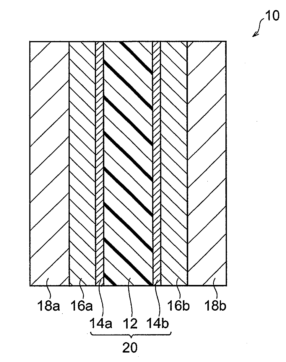
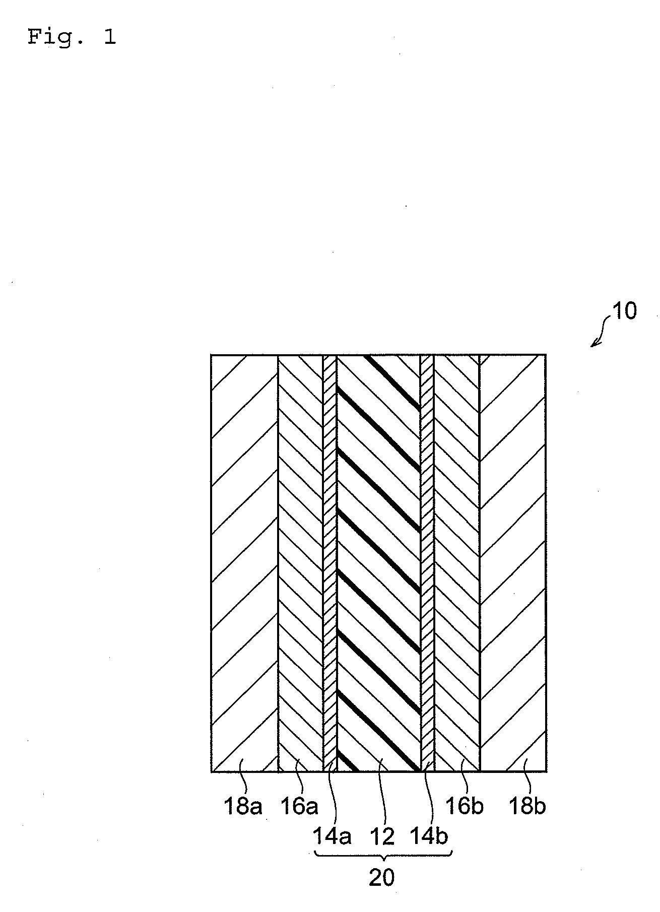
[0019]The present invention also provides a membrane-electrode assembly that has used the above-mentioned polymer electrolyte of the present invention. That is, the membrane-electrode assembly of the present invention has features that it has a polymer electrolyte membrane and a catalyst layer formed on this polymer electrolyte membrane, and that the polymer electrolyte membrane contains the above-mentioned polymer electrolyte of the present invention. Moreover, it may be said that the membrane-electrode assembly of the present invention has features that it has a polymer electrolyte membrane and a catalyst layer formed on this polymer electrolyte membrane, and that the catalyst layer contains the above-mentioned polymer electrolyte of the present invention and a catalyst. Such a membrane-electrode assembly is excellent in proton conductivity and can produce electric power at high efficiency, and further becomes small in dimensional change caused by the operation and stop and excellent in durability, because the polymer electrolyte membrane and / or the catalyst layer contains the polymer electrolyte of the present invention.
[0020]Further, the present invention provides a fuel cell having the above-mentioned membrane-electrode assembly of the present invention. That is, the fuel cell of the present invention has features that it has one pair of separators and a membrane-electrode assembly arranged between this one pair of separators, and that the membrane-electrode assembly is the above-mentioned membrane-electrode assembly of the present invention. Such membrane-electrode assembly can produce electric power at high efficiency, and further becomes excellent in durability, because it has the above-mentioned membrane-electrode assembly of the present invention.

Problems solved by technology

However, when the polymer electrolyte membrane by the above-mentioned conventional technology is used, the fuel cell often can not exhibit sufficient output and has tended to be difficult to certainly reach the operation with high efficiency.
In such a polymer electrolyte membrane, it became clear that not only resistance in the surface direction was lowered but a fuel cell with sufficiently high efficiency may not be provided.

Method used


Image

  • Polymer electrolyte, and polymer electrolyte membrane, membrane-electrode assembly and fuel cell that are using the polymer electrolyte
  • Polymer electrolyte, and polymer electrolyte membrane, membrane-electrode assembly and fuel cell that are using the polymer electrolyte
  • Polymer electrolyte, and polymer electrolyte membrane, membrane-electrode assembly and fuel cell that are using the polymer electrolyte

Examples


synthesis example 1

[0140]In a flask with an azeotropic distillation apparatus, 65.22 g of 4,4′-difluorodiphenylsulfone, 42.63 g of 2,6-dihydroxynaphthalene (Dainippon Ink And Chemicals, Incorporated), 608 g of N-methyl-pyrrolidone (NMP), and 99 g of toluene were added under an argon atmosphere, and argon gas was bubbled for one hour while stirring at room temperature. After that, 40.45 g of potassium carbonate was added and subjected to azeotropic dehydration by heating at 140° C. while stirring. After that, heating was continued while distilling and removing toluene and polymer J1 was obtained. Total heating time was five hours. The reaction liquid of the obtained polymer J1 was let alone and cooled at room temperature, and then used in the next reaction.

[0141]When weight average molecular weight (Mw) and number average molecular weight (Mn) of Polymer J1 were measured respectively, Mw was 8.3×10⁴ and Mn was 4.6×10⁴. These values are the values obtained by measuring with gel permeation chromatography...

synthesis example 2

[0149]In a flask with an azeotropic distillation apparatus, 83.70 g of 4,4′-difluorodiphenylsulfone, 53.31 g of 2,6-dihydroxynaphthalene, 606 g of NMP, and 102 g of toluene were added under an argon atmosphere, and argon gas was bubbled for one hour while stirring at room temperature. After that, 52.44 g of potassium carbonate was added and subjected to azeotropic dehydration by heating at 140° C. while stirring. After that, heating was continued while distilling and removing toluene and polymer J2 was obtained. The total heating time was 16.5 hours. Mw of polymer J2 was 1.1×10⁵, and Mn was 5.0×10⁴. The reaction liquid of the obtained polymer J2 was let alone and cooled at room temperature, and then used in the next reaction.

[0150]Moreover, in a flask with an azeotropic distillation apparatus, 98.53 g of 4,4′-difluorodiphenylsulfone-3,3′-dipotassium disulfonate, 40.01 g of 2,5-dihydroxybenzene potassium sulfonate, 600 g of dimethyl sulfoxide, and 94 g of toluene were added under an ...

synthesis example 3

[0154]In a flask with an azeotropic distillation apparatus, 249.01 g of 4,4′-difluorodiphenylsulfone, 164.60 g of 2,6-dihydroxynaphthalene, 902 g of NMP, and 294 g of toluene were added under an argon atmosphere, and argon gas was bubbled for one hour while stirring at room temperature. After that, 156.1 g of potassium carbonate was added and subjected to azeotropic dehydration by heating at 140° C. while stirring. After that, heating was continued while distilling and removing toluene and polymer J3 was obtained. The total heating time was 18.5 hours. Mw of polymer J3 was 7.4×10⁴, and Mn was 4.0×10⁴. The reaction liquid of the obtained polymer J3 was let alone and cooled at room temperature, and then used in the next reaction.

[0155]Moreover, in a flask with an azeotropic distillation apparatus, 284.3 g of 4,4′-difluorodiphenylsulfone-3,3′-dipotassium disulfonate, 120.0 g of 2,5-dihydroxybenzene potassium sulfonate, 1778 g of dimethyl sulfoxide, and 279 g of toluene were added under...


PUM

PropertyMeasurementUnit
ion-exchange capacityaaaaaaaaaa
temperatureaaaaaaaaaa

Abstract

The present invention provides polymer electrolyte that has the ion-exchange capacity of 1.7 meq/g or more and has the reduced viscosity of 160 mL/g or more at 40° C. when being made to be 1% by weight solution with at least one kind of solvent selected from the group consisting of N,N-dimethylformamide, N-methyl-2-pyrrolidone, dimethyl sulfoxide, N,N-dimethylacetamide, sulfolane, and γ-butyrolactone, and polymer electrolyte that has the ion-exchange capacity of 1.7 meq/g or more and the reduced viscosity of 160 mL/g or more at 40° C. when being made to be 1% by weight solution with at least one kind of solvent selected from the group consisting of N,N-dimethylformamide, N-methyl-2-pyrrolidone, and dimethyl sulfoxide.

Description

TECHNICAL FIELD[0001]The present invention relates to polymer electrolyte, and to polymer electrolyte membrane, membrane-electrode assembly and fuel cell that are using the polymer electrolyte.BACKGROUND ART[0002]As a proton conductive membrane in a solid polymer type fuel cell, a proton conductive membrane made of a proton conductive polymer electrolyte membrane is used. In recent years, as an electric generator for a house and automobile, the practical application of the solid polymer type fuel cell is expected, and as for such fuel cells, it is required to be possible to be operated at higher power generation efficiency than ever before.[0003]One of the way to make it possible to operate at high efficiency is to enhance the proton conductivity of the proton conductive membrane, and it is necessary to heat the proton conductive membrane (a polymer electrolyte membrane) enough to make sure of high proton conductivity. Moreover, during operation of the fuel cell (during power genera...

Claims


Application Information

Patent Timeline
Patent Type & Authority Applications(United States)
IPC IPC(8): H01M8/10
CPCC08J5/2256C08J2381/06H01M8/1027H01M8/1032H01M8/106H01M8/1062C08J2387/00H01M2008/1095H01M2300/0082H01M2300/0094Y02E60/521C08J2471/12H01M8/1081H01B1/122H01M8/1067H01M8/1069Y02P70/50Y02E60/50H01M8/10H01M4/86
Inventor SAITO, SHINIWASAKI, KATSUHIKOYOSHIMURA, KENYAMADA, TAKASHI
Owner SUMITOMO CHEM CO LTD
Why Eureka
Try Eureka