Method of triggering a ventilator

a ventilator and a technology of a trigger device, which is applied in the field of triggering a ventilator, can solve the problems of affecting the operation of the operating means/releasing device of the valve, affecting the successful separation of the patient from the intubation tube, and affecting the patient's recovery, etc., so as to achieve the effect of simple operation and accelerate patient weaning

Inactive Publication Date: 2009-05-14
KIMBERLY-CLARK WORLDWIDE INC
View PDF19 Cites 50 Cited by
  • Summary
  • Abstract
  • Description
  • Claims
  • Application Information

AI Technical Summary

Benefits of technology

[0002]State of the art intensive care ventilators enable a medical professional such as a therapist to set, sense or control respiratory parameters such as tidal volume, respiratory rate, respiratory minute volume, flow pattern overtime, time ratio between the inspiration and expiration phase, amplitude of the breathing gas flow, respiratory pressure at the end of an inspiration phase, peak airway pressure, positive end-expiratory pressure (PEEP), as well as volume or flow gradients within the ventilation tubing circuit, thus triggering ventilator generated assist for a spontaneously breathing patient. The diversity of respiratory parameters, in the majority of cases, allows a sufficiently comfortable and safe interaction between ventilator and patient.
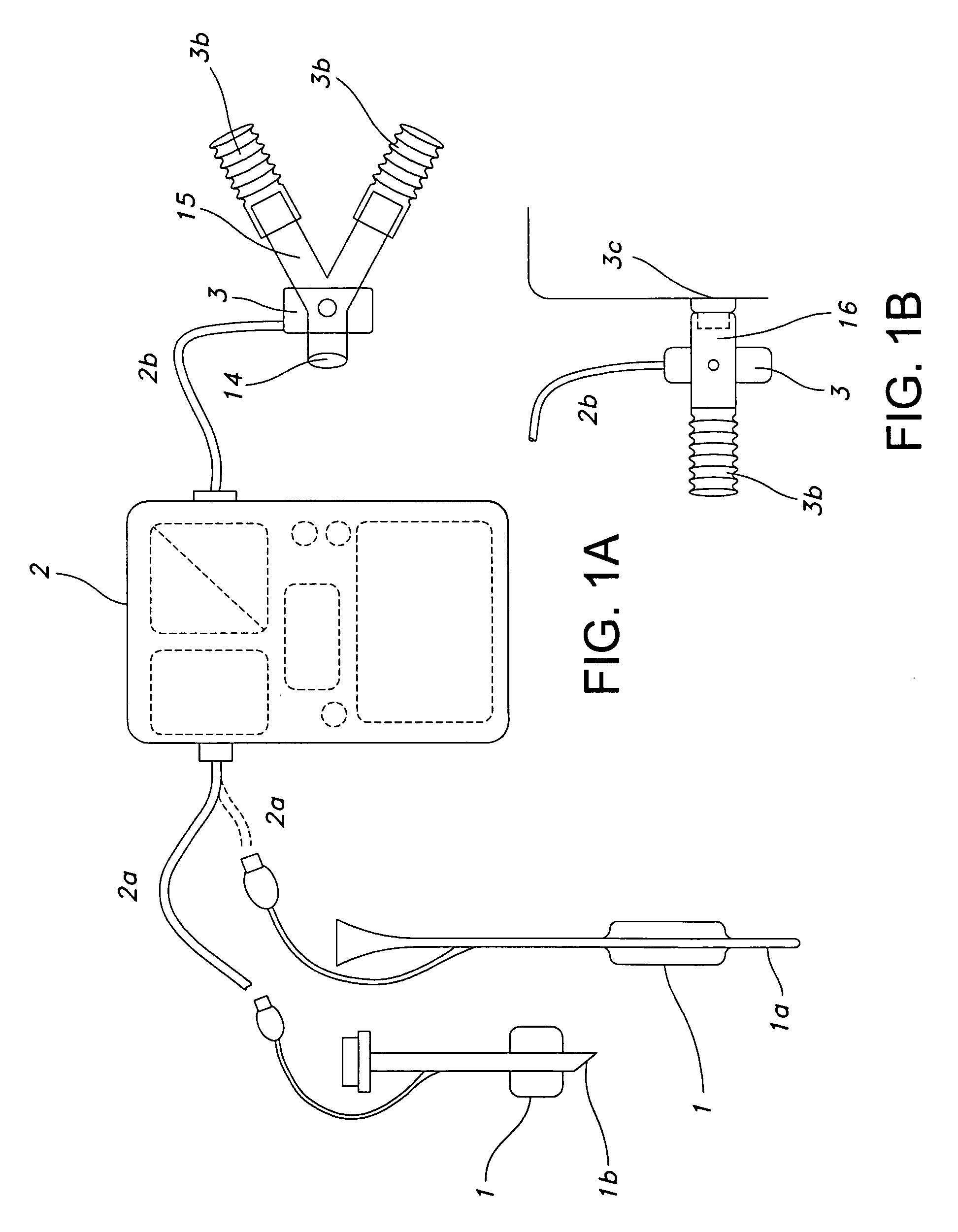
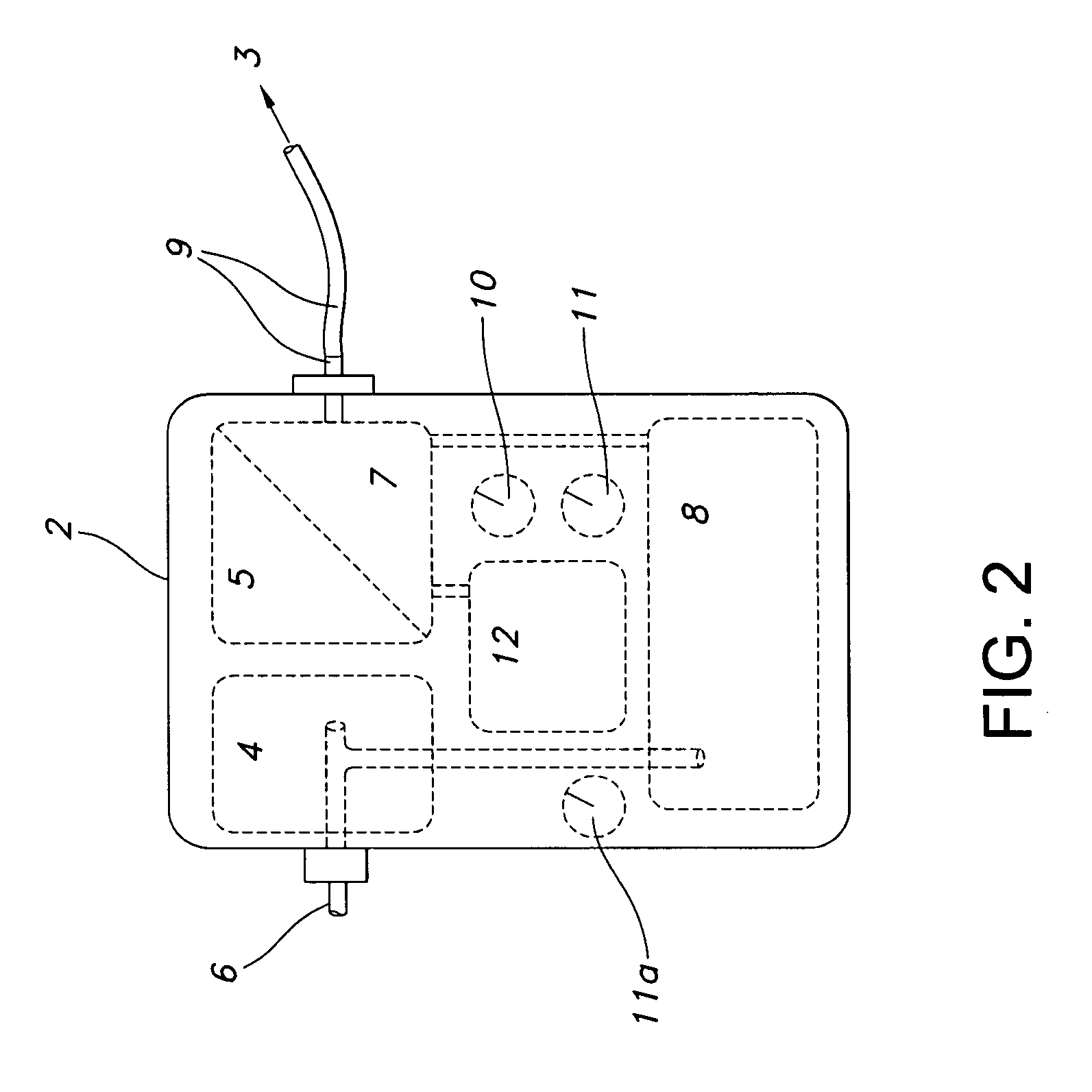
[0022]Subsequent to sensing the initial decrease in intra-chest pressure, marking the onset of patient breathing activity, a pressure release valve which is inserted into the ventilation tubing circuit is opened, thus initiating a pressure drop or flow change inside the ventilation tubing, whereby the generated pressure or flow gradient is sufficiently large to be sensed by the ventilator integrated pressure or flow sensors. The associated work of breathing which is performed by the patient can thus be minimized and to a large degree controlled by the therapist. Respiratory fatigue of the patient in the transition phase from controlled to assisted patient ventilation can be reduced or prevented and patient weaning accelerated.

Problems solved by technology

In patients with reduced or deteriorated respiratory muscular performance, as can be observed after prolonged periods of tracheal intubation and controlled positive pressure ventilation, the transition from controlled respiratory modes, (wherein the patient is not actively contributing to the exchange of ventilation gas and the ventilation parameters are completely determined by the therapist) to assisted ventilation, (wherein the patient is actively breathing while also receiving tidal support from the ventilator which is sensing and assisting the patients own breathing efforts) can be difficult.
This can considerably delay the successful separation of the patient from the intubation tube and the ventilator, also called patient weaning.
Though the respiratory regulatory functions may be intact, in numerous patients, especially those coming out of a prolonged period of intensive sedation and fully controlled mechanical ventilation, the muscular and mechanical performance of the patent's breathing apparatus can be weakened and deteriorated to such a degree that it is impossible for the patient to release tidal support from the mechanical ventilator and to enter into a sustaining, patient determined, machine assisted breathing rhythm.
Patients whose chest's are mechanically incapable of generating a triggering shift of ventilation gas into the lower airways or are incapable of generating a sufficiently large pressure drop within the patient supplying ventilation tubing, do not receive respiratory support by the ventilator.
The chest muscular and diaphragmatic work by a clinically not-breathing and not-triggering patient may be considerable and, over time, cause fatiguing of the respiratory performance.
Patient breathing activity that is, however, insufficient to release ventilator support, can result from various conditions:
Due to structural (often fibrotic) changes in the lung tissue (an associated stiffening of the lung and a loss of lung tissue compliance) or for example, changes in the composition of the alveolar surfactant, the respiratory apparatus is not able to overcome the initial elasticity of the lungs, which is necessary to open up the various lung compartments, increase their volume and thereby generate the pressure gradient between the distal airways and the patient connected ventilation tubing which is the driving force of external gas exchange.
Such isometric or nearly isometric muscle action is usually performed at a high frequency, typically deteriorating in intensity over time, and in many cases leading to the state of total chest mechanical arrest.
In other cases, patients are capable of triggering ventilator support intermittently, yet continue to perform a large number of unproductive isometric breathing actions in between the respirator supported breaths, which are not sensed by the sensor components and remain unnoticed by the ventilator as actual patient breathing activity.
In further cases, conventional ventilator assist may fail or take place only intermittently because of the flow resistance caused by the patient connected ventilation circuit and / or patient intubated tubing itself.
In all such cases of isometric muscle action without any volume productive lung expansion (or with an insufficient lung expansion) leading to an insufficient pressure gradient between the distal end of the tracheal tube and the location of the flow or pressure sensing element of the ventilator, or in cases of intermittently triggered support (wherein a significant number of isometric or insufficient respiratory attempts is not sensed and responded by the ventilator) the patient may be performing considerable of work of breathing, over time exhausting his chest muscular and diaphragmatic capabilities and eventually resulting in respiratory fatigue and total mechanical arrest.
Yet such EMG based interfaces with the patient are expensive, require complex programming and have not been integrated into ventilators.
The small bore pressure measuring channels, however, rapidly plug up with secretions and not clinically reliable.
The method is technologically complex, requires specially designed tracheal tubes and has to be suited to the individual ventilator type.
Furthermore, respirator triggering on the basis of central airway pressure changes is not capable of sensing the onset of merely isometric breathing work, not resulting in any or only a small shift of ventilation volume.
The technology has been shown to be very receptive to artefacts and is therefore difficult to operate in clinical routine.
Unfortunately, the impendance based signal can be easily disrupted by cardiac artefacts, lead placement, or change in body position.

Method used


Image

  • Method of triggering a ventilator
  • Method of triggering a ventilator
  • Method of triggering a ventilator

Examples


Embodiment Construction

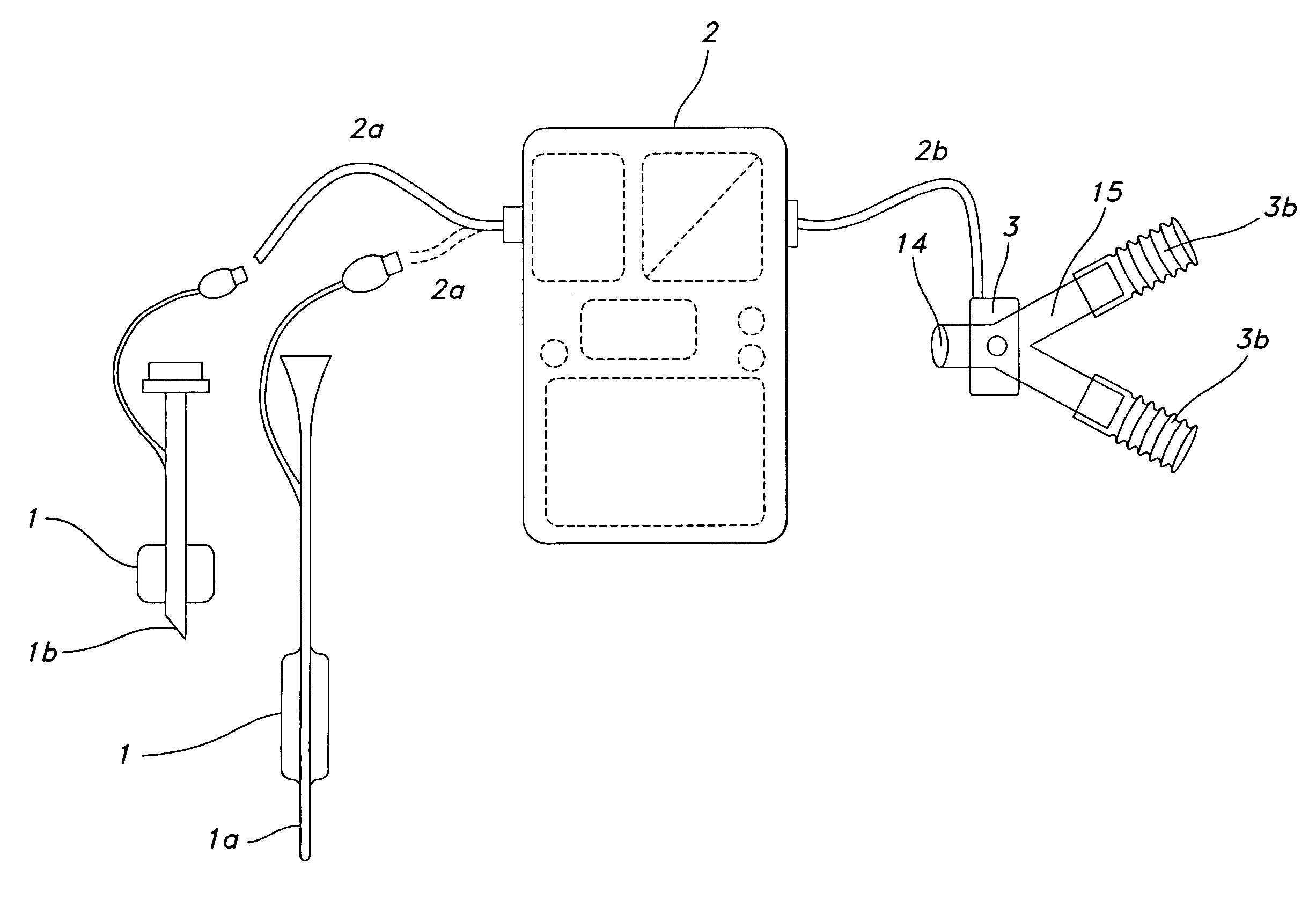
[0027]The following describes a technology / device developed to accelerate and better control the transition from controlled to assisted (or supported) ventilation modes. By triggering ventilator support on the basis of the detection of relative changes in the intra-chest pressure (intra-thoracic pressure) of a patient, patients can be converted to assisted breathing significantly earlier, and in a manner not requiring any direct communication between the inventive device and the ventilator. As such, the invention represents a relatively simple, easy to apply, universally compatible device for more efficient patient weaning.

[0028]The beginning of a breathing cycle can be detected either by a chest volume expansion associated pressure change inside the cuff of a tracheal or tracheostomy tube. Alternatively, an intra-thoracic pressure change can be detected by a pressure sensing element located in the esophageal section of a naso-gastric tube (NG tube).

[0029]Tracheal or tracheostomy tu...


PUM


Abstract

There is provided a method for controlling breathing gas flow of a ventilator for assisted or controlled ventilation of a patient as a function of a intra-thoracic airway pressure of the patient using a tracheal tube or naso-gastric tube. The intra-thoracic pressure is transmitted to a controller and the information detected is used to control a valve to vent gas from the inhalation tubing of the ventilator, thus triggering an inhalation cycle in the ventilator.

Description

[0001]In intensive care therapy, ventilators or respirators are used for mechanical ventilation of the lungs of a patient. The ventilator unit is connected to a hose set; the ventilation tubing or tubing circuit, delivering the ventilation gas to the patient. At the patient end, the ventilation tubing is typically connected to a tracheal ventilation catheter or tube, granting direct and secure access to the lower airways of a patient. Tracheal catheters for critical care ventilation are equipped with an inflated sealing balloon element, or “cuff”, creating a seal between the tracheal wall and tracheal ventilation tube shaft, permitting positive pressure ventilation of the lungs.[0002]State of the art intensive care ventilators enable a medical professional such as a therapist to set, sense or control respiratory parameters such as tidal volume, respiratory rate, respiratory minute volume, flow pattern overtime, time ratio between the inspiration and expiration phase, amplitude of th...

Claims


Application Information

Patent Timeline
Patent Type & Authority Applications(United States)
IPC IPC(8): A61M16/00
CPCA61B5/037A61M16/0051A61M16/04A61M16/044A61M16/0465A61M16/20A61M16/209A61M2016/0027A61M2205/3569A61M2205/3592A61M2205/502A61M16/0833A61M16/202A61M2016/0021A61M16/0858A61M16/024
Inventor GOEBEL, FRED
Owner KIMBERLY-CLARK WORLDWIDE INC
Why Eureka
Try Eureka