Heat transfer member, convex structural member, electronic apparatus, and electric product

a technology of convex structure and heat transfer member, which is applied in the direction of lighting and heating apparatus, laminated elements, and semiconductor/solid-state device details. it can solve the problems of large angle to the external periphery, limited size, and considerable thickness increase of cathode-ray tube televisions. achieve rapid heating, increase heat output, and increase efficiency

Inactive Publication Date: 2009-05-21
SUMITOMO ELECTRIC IND LTD
View PDF11 Cites 28 Cited by
  • Summary
  • Abstract
  • Description
  • Claims
  • Application Information

AI Technical Summary

Benefits of technology

[0019]In accordance with the heat transfer member of the present invention, a heat transfer member can be mounted in close contact with a cooled body without the use of a polymer, organic sheet, or grease in a conventional manner and without producing gaps that cause heat resistance, by using columnar body structures that have elastic deformability and / or plastic deformability, even if warping, roughness, and the like are present in an element, a substrate on which the element is mounted, or another cooled body. As a result, heat transferred from the contacted body through the columnar body structure can be immediately radiated to a coolant, or the contacted body can be rapidly heated.
[0020]Therefore, a contacted body can be rapidly heated or heat can be dissipated with greater efficiency by using the heat transfer member of the present invention in comparison with a conventional heat sink, fins and a fan, or another cooling means that use a polymer, an organic sheet, or grease. The recent increase in heat output can therefore be managed in, e.g., televisions, projectors, personal computers, automobiles, and other electronic apparatuses and electric products, and the high throughput and highly uniform heating characteristics in semiconductor manufacturing apparatuses, heaters, and the like can be managed.
[0021]In accordance with the convex structural member of the present invention, a heat transfer member can be mounted in close contact with a cooled body without the conventional use of a polymer, organic sheet, or grease and without producing gaps that cause heat resistance, by using a convex structural unit that has the ability to elastically deform and / or plastically deform, even if warping, roughness, and the like are present in an element that requires high-efficiency cooling, in a substrate on which the element is mounted, in a component that requires rapid heating or cooling, or in a cooled body. As a result, heat can be rapidly taken and radiated away from the contacted body, or can be rapidly transferred to the contacted body, and the member can be manufactured at low cost.
[0022]Therefore, it is possible to mass produce a member in which the heat dissipation efficiency or heat supply efficiency can be increased by using the convex structural member of the present invention in comparison with a conventional thermal conductive element in which a polymer, organic sheet, or grease is used. It is therefore possible to rapidly heat or to efficiently manage the recent increase in the heat output of, e.g., electronic apparatuses, household appliances, and industrial products.

Problems solved by technology

However, since a television that uses this method scans the cathode-ray tube using a single electron gun, the angle to the external periphery becomes considerable when the size of the monitor is increased, and the ability to increase the size is limited because the monitor becomes distorted.
Also, a cathode-ray tube television considerably increases in thickness as the size of the monitor increases, and such a large-monitor television is not suitable for installation in the living room of a common home.
There is also a demand for greater brightness because light diffuses to a greater extent and the monitor becomes darker and more difficult to view as the size of the monitor increases.
Also, since the luminous energy per unit area is insufficient when display is made to a large monitor using the same output, power consumption generally increases as the size of the monitor increases, and heat output increases in accordance therewith.
As a result, the elements and peripheral equipment will suffer thermal degradation if the heat is not efficiently dissipated from the system, and there is an increasing need to efficiently dissipate heat.
Currently, however, heat dissipation techniques have not caught up to the considerable increase in heat output.
However, a metallic expanded body has innumerable holes, and if incorrectly used, the metallic expanded body, rather than providing heat radiation properties, is liable to act as an insulation layer due to the internal air holes, such as in highly insulative expanded polystyrene and the like.
However, it is difficult to bring about direct gapless contact with the heat radiation area because the high-porosity area does not deform, as exemplified by a porous sintered body or a ceramic fiber.

Method used


Image

  • Heat transfer member, convex structural member, electronic apparatus, and electric product
  • Heat transfer member, convex structural member, electronic apparatus, and electric product
  • Heat transfer member, convex structural member, electronic apparatus, and electric product

Examples


embodiment 1

[0057]Warping, waviness, surface roughness, and other shapes that cannot be perfectly suppressed are commonly present in a cooled body, gaps are therefore generated in the surface of contact with the heat sink, and the gaps have substantially no thermal conductivity, resulting in a considerable hindrance to heat transfer. When highly rigid components are placed in contact with each other, for example, a perfectly flat surface cannot be formed when viewed microscopically, no matter how much the planarity is increased and the surface roughness is reduced. As a result, the three most projecting points make contact, and the other parts remain suspended. Therefore, gaps produced between components do not contribute to heat transfer, and cooling capacity is unavoidably reduced.

[0058]In view of this situation, it has conventionally been necessary to use grease, an organic sheet, or a highly effective space-filling polymer to fill in gaps between components. However, the thermal conductivit...

embodiment 2

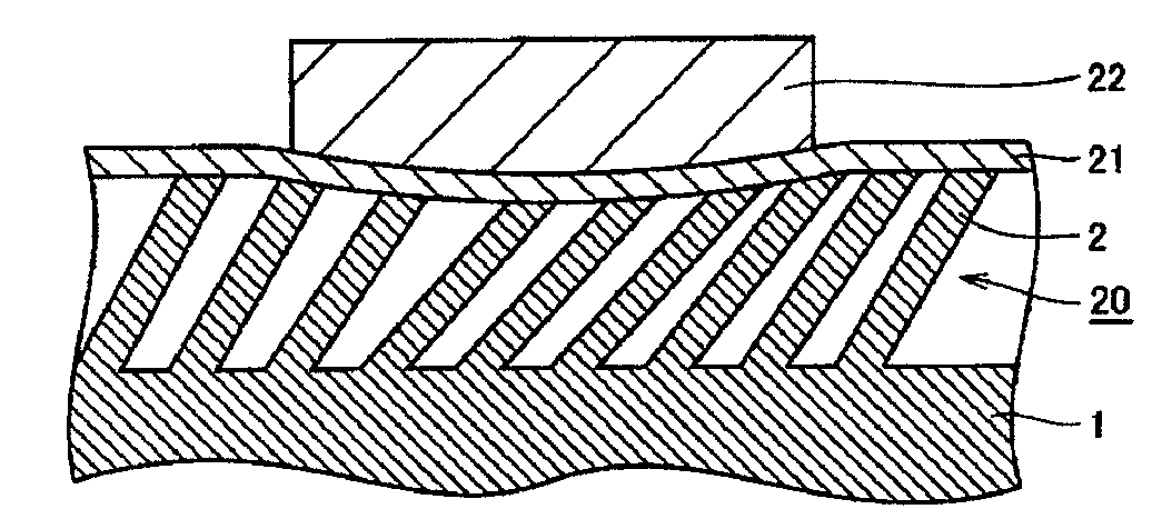
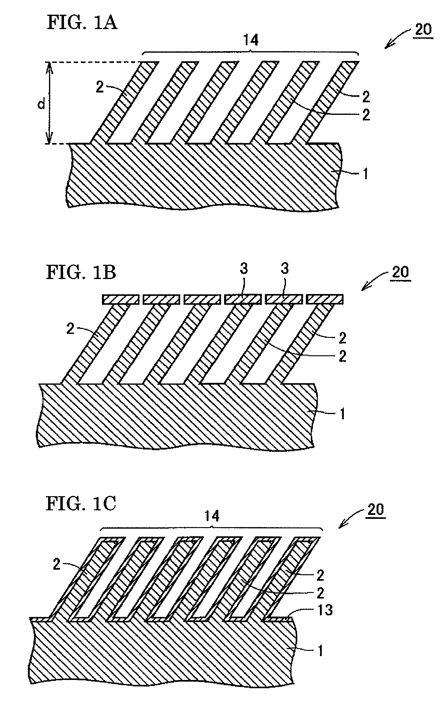
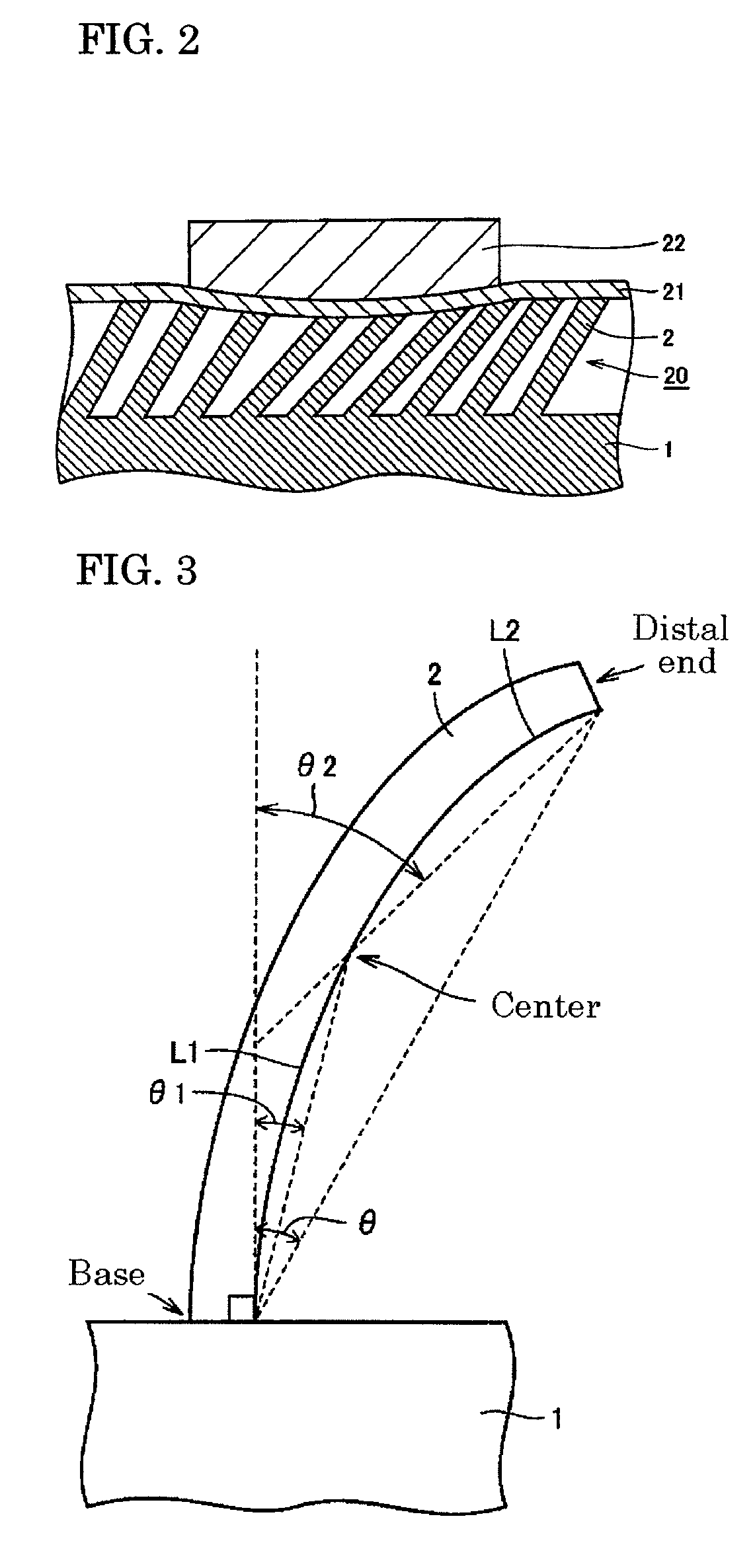
[0102]The convex structural member of the present invention is a member having a plurality of convex structures supported on a support, wherein all or some of the convex structures are in contact with a contacted body and undergo elastic and / or plastic deformation along the shape of a contact surface of the contacted body. Heat is therefore moved via the convex structural unit because the convex structure can be in direct contact along the wavy and rough irregularities of the cooled body and is in direct contact with the contacted body. In other words, direct gapless contact can be made with a contacted body, and the heat of the contacted body can be taken away or be supplied to the contacted body. A contacted body can be rapidly brought to a prescribed temperature because heat is rapidly transferred from a higher-temperature region to a lower-temperature region via a convex structural unit that is in contact with the contacted body.

[0103]In one mode of the convex structural member ...

example 1

[0125]An AlN heater 4 having longitudinal, horizontal, and thickness dimensions of 20×20×1 mm was used in place of a semiconductor element, as shown in FIG. 11, and the AlN heater 4 was bonded to an Al2O3 substrate 5 having a purity of 92% and longitudinal, horizontal, and thickness dimensions of 40×40×2.5 mm, respectively, by using Ag grease (thermal conductivity: 9 W / m·K). The contact area in the center of the reverse side of the Al2O3 substrate 5, which was a contacted body, had a length of 20 mm and a width of 20 mm and was concavely warped by 0.05 mm.

[0126]A columnar body assembly 7 composed of an assembly of numerous Cu columnar bodies on one side of a Cu base 6, which was a support, were also formed by electrical discharge machining to serve as the heat transfer member 20. A Cu plate-like body 8 for radiating heat was disposed on the other surface of the Cu base 6, and fins 9 were formed by integral machining on the rear surface of the Cu plate-like body 8. The columnar bodie...


PUM

PropertyMeasurementUnit
inclined angleaaaaaaaaaa
thicknessaaaaaaaaaa
thermal conductivityaaaaaaaaaa

Abstract

A heat transfer member (20) has a support (1), and columnar bodies (2) all or some of which are disposed so as to be inclined at an angle with respect to the support (1). The columnar bodies (2) are in contact with a contacted body (21), and the columnar bodies (2) elastically deform and / or plastically deform along the shape of the contact surface with the contacted body (21) to thereby make direct contact along the wavy and rough irregularities of the contacted body (21), and to cause heat to move through the columnar bodies (2).

Description

TECHNICAL FIELD[0001]The present invention relates to a heat transfer member, a convex structural member, an electronic apparatus, and an electric product for rapidly removing heat from required locations and rapidly supplying heat to required locations of an electronic apparatus, a household electric appliance, or an industrial product.BACKGROUND ART[0002]The electron gun method that uses a cathode-ray tube has conventionally been the common method for projecting an image to a monitor in a television (TV). However, since a television that uses this method scans the cathode-ray tube using a single electron gun, the angle to the external periphery becomes considerable when the size of the monitor is increased, and the ability to increase the size is limited because the monitor becomes distorted. One method for preventing distortions in the monitor is to curve the monitor to maintain a constant distance between the electron gun and the cathode-ray tube. However, a flat monitor is easi...

Claims


Application Information

Patent Timeline
Patent Type & Authority Applications(United States)
IPC IPC(8): F28F9/00
CPCH01L23/3677H01L23/3735H01L23/433H05K7/20963H01L2924/0002H01L2924/00F28F3/048F28F13/18F28F19/02H01L23/36
Inventor KUIBIRA, AKIRANATSUHARA, MASUHIROAWAZU, TOMOYUKINAKATA, HIROHIKO
Owner SUMITOMO ELECTRIC IND LTD
Why Eureka
Try Eureka