High pressure-resistant type electrical deionization apparatus, high pressure-resistant type electrical deionization system and method of producing ultrapure water using high pressure-resistant type deionization system

a technology of electrical deionization system and high pressure resistance, which is applied in the direction of fluid pressure measurement, liquid/fluent solid measurement, peptide, etc., can solve the problems high cost of radioactive waste treatment, and limited exchange capacity so as to reduce the running cost of the entire plant and reduce the cost of regenerating and new ion exchange resin. , the effect of reducing the cost of ion exchange resin

Inactive Publication Date: 2009-05-21
EBARA CORP
View PDF2 Cites 4 Cited by
  • Summary
  • Abstract
  • Description
  • Claims
  • Application Information

AI Technical Summary

Benefits of technology

[0014]According to the high pressure-resistant type electrical deionization apparatus of the present invention, the raw water from ultra pure water production process using the middle-high pressure wherein the prior electric deionization stack is hardly applied due to the pressure resistance performance, can be directly flowed through the electrical deionization apparatus of the present invention without controlling the pressure using the reservoir tank and the pumps, the treated water with the pressure maintained can be delivered to the ultra pure water production process, and thus the replacement of the prior ion exchange apparatus with the high-pressure resistant type electrical deionization apparatus is accomplished. Thus, according to the present invention, the wastewater from the regeneration of ion exchange resin and the waste materials such as the used ion exchange resin can be significantly reduced, and the cost of chemicals for regeneration and new ion exchange resin is also reduced, whereby the running cost of the entire plant can be reduced.

Problems solved by technology

However, ion exchange resins have a limited exchange capacity.
In addition, a volume of expensive ion exchange resins are needed to periodically replace the used ion exchange resins.
This treatment of the radioactive waste is very expensive.
In particular, the used ion exchange resins are difficult to burn and to reduce in volume by incineration.
The used ion exchange resins are usually retained in storage facilities, causing a problem of storage capacity of the facilities.
However, the prior electrical deionization apparatus does not have high-pressure resistance, which is necessary to use the apparatus in the nuclear facilities dealing with radioactive material.
When the pressure above the range is applied to the stacked form of plastics frames, a leakage from sealing portions may occurred.
In addition, it was difficult to directly treat the raw water having middle-high pressure by use of the prior electrical deionization apparatus since it is necessary that the differential pressure between the pressure within the deionization compartment and the pressure within the concentrating compartment is below 0.05 MPa to prevent inner leakage of the prior electrical deionization apparatus.
Thus, when the prior electrical deionization apparatus is incorporated into the ultra pure water producing system in the high-pressure plants, the system is larger, causing problems that the investment in facilities becomes huge and the operation of the system is complex.
In fact, in particular, it is impossible to replace the existing ion exchange resin column in the atomic power plant with the electrical deionization apparatus due to space limitations for installation of the apparatus.
Further, when the reservoir tank is used to release the pressure of the wastewater from the high-pressure plants, oxygen and carbon dioxide from the air are dissolved into the raw water to increase the level of the impurities causing the increase of load against the treatment capacity.
In short, deterioration of water quality is caused in the case that the raw water from the high-pressure water utilization plants is treated by the prior electrical deionization apparatus, if the service water and the waste water are introduced into the prior electrical deionization apparatus without their pressure being controlled, the leakage from the deionization compartment is caused as well as the inner leakage being caused when the pressure within the concentrating compartment is not adequately controlled to meet the pressure within the desalt compartment.

Method used


Image

  • High pressure-resistant type electrical deionization apparatus, high pressure-resistant type electrical deionization system and method of producing ultrapure water using high pressure-resistant type deionization system
  • High pressure-resistant type electrical deionization apparatus, high pressure-resistant type electrical deionization system and method of producing ultrapure water using high pressure-resistant type deionization system
  • High pressure-resistant type electrical deionization apparatus, high pressure-resistant type electrical deionization system and method of producing ultrapure water using high pressure-resistant type deionization system

Examples


Embodiment Construction

[0022]The present invention will be explained by referring the drawings.

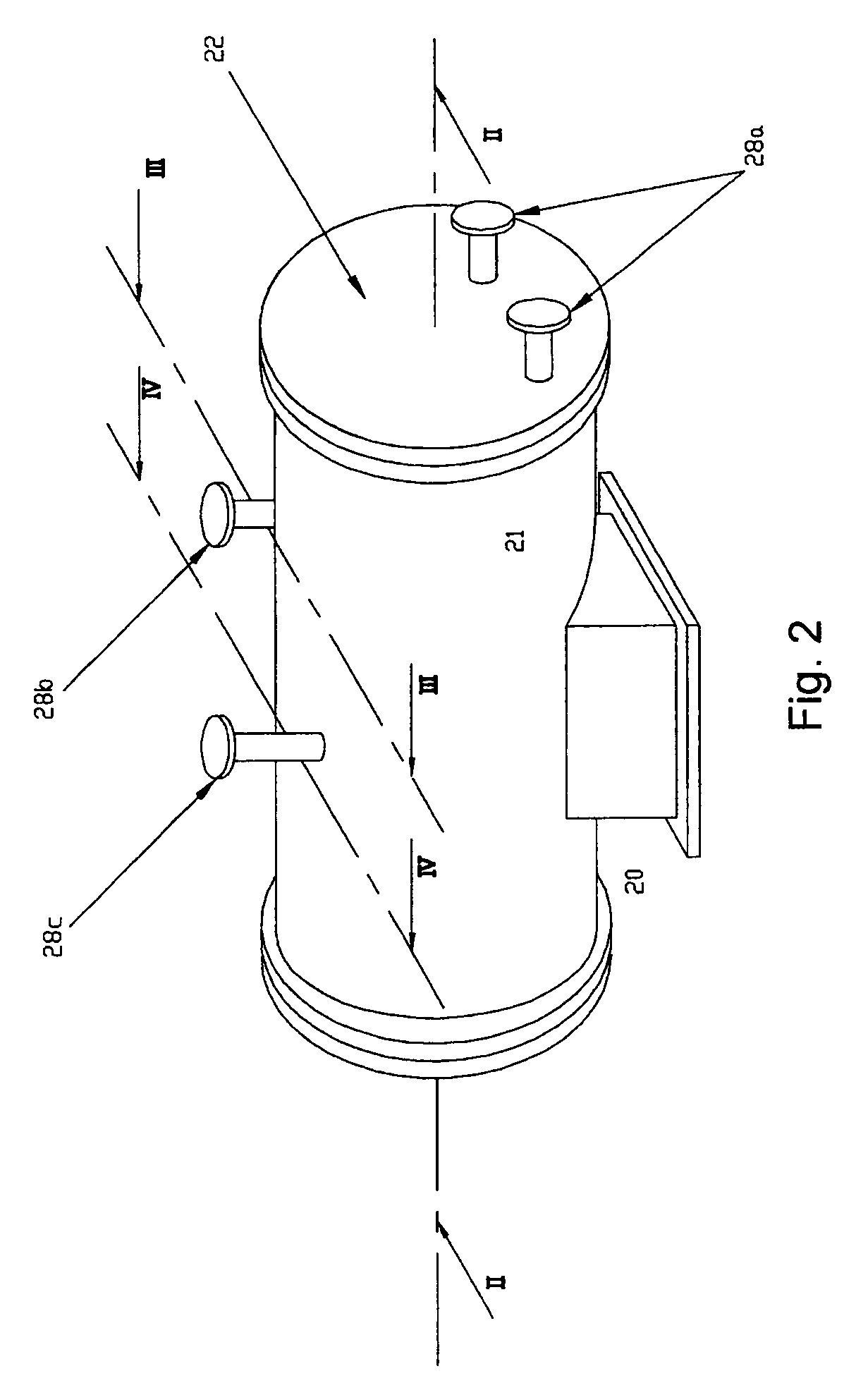
[0023]In the drawings, 1 indicates a high pressure-resistant type electrical deionization apparatus, 10 indicates an electric deionization stack, 11 indicates a compartment frame, 12 indicates an ion exchange membrane, 13 indicates an anode compartment, 14 indicates a cathode compartment, 15 indicates a concentrating compartment, 16 indicates a deionizing compartment, 17 indicates a concentrated water outlet, 18 indicates a treated water outlet, 19 indicates a liquid feeding line, 20 indicates a pressure vessel, 21 indicates a vessel body, 22 indicates a lid, 23 indicates a partition plate, 24 indicates a concentrated water chamber, 25 indicates a treated water chamber, 26 indicates an insulating and sealing member, 27 indicates an insulating lining, 28a indicates a feeding port, 28b indicates a concentrated water outlet, 28c indicates a treated water outlet, 29 indicates a mounting bolt for the lid, and 30 indi...


PUM

PropertyMeasurementUnit
pressureaaaaaaaaaa
pressuresaaaaaaaaaa
pressureaaaaaaaaaa

Abstract

The present invention provides an electrical deionization apparatus suitable for an ultra pure water production system allowing high pressure raw water from an atomic power plant to be reused as the ultra water. The electric deionization stack 10 comprises a plurality of compartments defined by a compartment frame 11 and an ion exchange membrane 12. The compartments at the opposite ends construct an anode compartment 13 and a cathode compartment 14. The compartments, which are located between the anode compartment 13 and the cathode compartment 14, construct at least one concentrating compartment 15 and at least one deionizing compartment 16. Each compartment frame 11a constructing the concentrating compartment 15 has a concentrated water outlet 17. Each compartment frame 11b constructing the deionizing compartment 16 has a treated water outlet 18. In the pressure vessel 20, a concentrated water chamber 24 and a treated water chamber 25 are partitioned by a partition plate 23. Into the concentrated water chamber 24, the concentrated water flows from the concentrated water outlet 17 of the electric deionization stack 10. Into the treated water chamber 25, the treated water flows from the treated water outlet 18.

Description

BACKGROUND OF THE INVENTION[0001]The present invention relates to an electrical deionization system suitable for producing ultra pure water, in particular, a high pressure-resistant type electrical deionization system for treatment of service water and wastewater in a field where instruments such as nuclear facilities are required to meet strict standards defined by laws and regulations.[0002]Typically, in treatment facilities for service water and wastewater in facilities using radioactive materials, such as an atomic power plant, an ion exchange apparatus using particulate ion exchange resin has been used to remove ionic components as impurities. Such an apparatus removes impurity ions by flowing raw water through an ion exchange column filled with ion exchange resins.[0003]However, ion exchange resins have a limited exchange capacity. It is necessary to replace broken through ion exchange resins with new ion exchange resins or to regenerate used ion exchange resins with a regener...

Claims


Application Information

Patent Timeline
Patent Type & Authority Applications(United States)
IPC IPC(8): C02F1/469B01J47/14
CPCB01D61/48B01D61/54C02F2209/03C02F1/4695C02F2103/04B01D2313/20Y02A20/124
Inventor MIURA, SHINJIUENO, SYUICHI
Owner EBARA CORP
Why Eureka
Try Eureka