Optical system and atomic oscillator background

an atomic oscillator and optical system technology, applied in the field of optical systems of atomic oscillators, can solve the problems of increasing the height of the entire optical system, increasing the complexity of adjustment, and less desirable s/n characteristics, and achieves the effects of improving signal-to-noise characteristics, reducing the length of bonding wiring, and being easy to moun

Inactive Publication Date: 2009-05-21
SEIKO EPSON CORP
View PDF12 Cites 26 Cited by
  • Summary
  • Abstract
  • Description
  • Claims
  • Application Information

AI Technical Summary

Benefits of technology

[0008]An advantage of the present invention is to provide an atomic oscillator that includes an optical system that has improved signal-to-noise (S / N) characteristics and is easily mounted as a module. This is achieved by reducing the length of the bonding wiring electrically coupled with the receiving element, using a structure where a light receiving element and a light emitting element are closely arranged on the same side relative to the gas cell. In the structure, light emitted from a light emitting element is shifted by λ / 4 with a polarizing element and turned back, so that light travels back and forth inside a gas cell with orthogonal polarization states converted by the polarization element and is separated by a polarization separating element to change the optical path.
[0009]According to a first aspect of the invention, an optical system of an atomic oscillator includes: a coherent light source emitting two resonant light components each having a p-polarized light component or an s-polarized light component, the two resonant light components being coherent light and having a different frequency each other; a polarization splitter arranged at an output side of the coherent light source, the polarization splitter transmitting one of the p-polarized light component and the s-polarized light component and changes an optical path of the other of the p-polarized light component and the s-polarized light component to be outputted; a quarter-wave plate arranged at an output side of the polarization splitter so as to convert one of circularly polarized light and linearly polarized light to the other of circularly polarized light and linearly polarized light; a gas cell in which metal atom vapor is enclosed; a light guide that guides light after passing through the gas cell back to the gas cell as turned-back light; and a photodetector that detects the turned-back light, the turned-back light having been passed through the gas cell and changed the optical path by the polarization splitter. In this optical system, the atomic oscillator controls an oscillation frequency by using a light absorption characteristic caused by a quantum-interference effect when the two resonant light components are incident on the optical system.
[0010]The atomic oscillator uses the quantum interference effect of the coherent light such as laser light. In a three-level system (for instance, a Λ (lambda) type level system), two ground levels each receiving a resonant light component are in a resonant coupling state relative to a common excitation level. Here, if the frequency difference between the two resonant light components irradiated simultaneously accurately match the energy difference between a ground level 1 and a ground level 2, then the three-level system becomes a state of superposition of the two ground levels. As a result, the excitation to an excitation level 3 is stopped. CPT uses this principle in order to detect a state in which the light absorption in the gas cell stops when one or both of the two wavelengths of the resonant light components change.
[0011]In the optical system, the coherent light source and the photodetector are both mounted on the same side relative to the gas cell, and the polarization splitter transmits a p-polarized light component included in the resonant light component emitted from the coherent light source, and the quarter-wave plate converts the p-polarized light component to circular polarized light. The circularly polarized light passes through the gas cell, and after being reflected by the light guide, passes through the gas cell again. Thereafter, the quarter-wave plate converts the circularly polarized light to linearly polarized light, i.e., the s-polarized light component. Then, the s-polarized light component is detected by the photodetector. Consequently, the polarization splitter allows the resonant light components to travel back and forth inside the gas cell.
[0012]Moreover, the circularly polarized light passing through the gas cell may be reflected by the light guide so as to turn back a same optical path.
[0013]A phenomenon called Doppler Broadening occurs when light passes through the gas cell. This phenomenon is expected to be canceled by light traveling back and forth along the same optical path. Therefore, in the optical system, the light guide is arranged so that the light that has passed through the gas cell passes the same optical path so as to cancel the Doppler broadening.

Problems solved by technology

Moreover, signals obtained at the light receiving element 90 are weak, making the module susceptible to effects of noise superimposed on wires, thereby resulting in less desirable S / N characteristics.
As a result, it is necessary to adjust the angle of the reflection mirror 110, increasing the complexity in the adjustment.
Moreover, the inclination of the reflection mirror 110 results in a height increase of the entire optical system, which goes against the miniaturization of the optical system.

Method used


Image

  • Optical system and atomic oscillator background
  • Optical system and atomic oscillator background
  • Optical system and atomic oscillator background

Examples


first embodiment

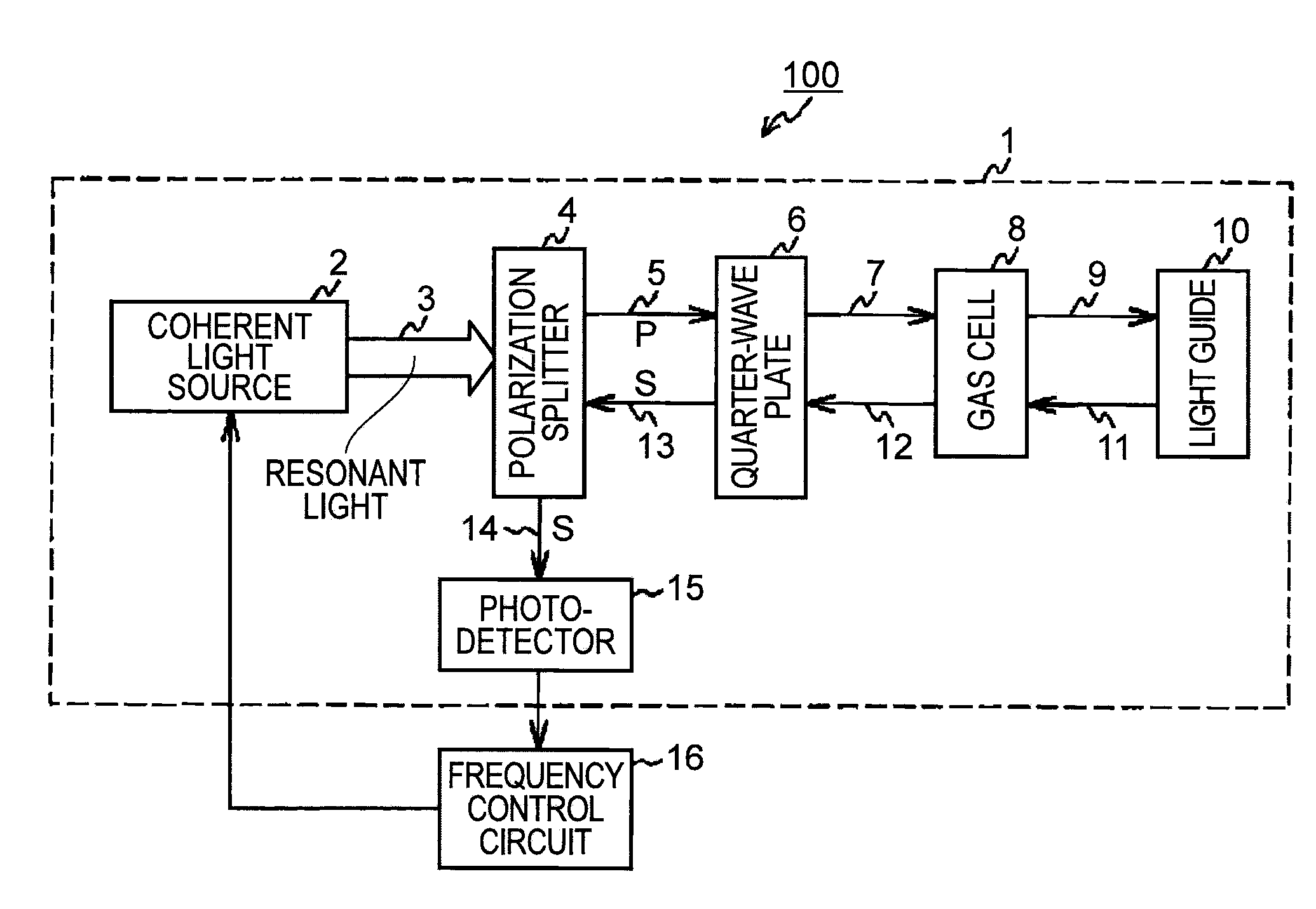
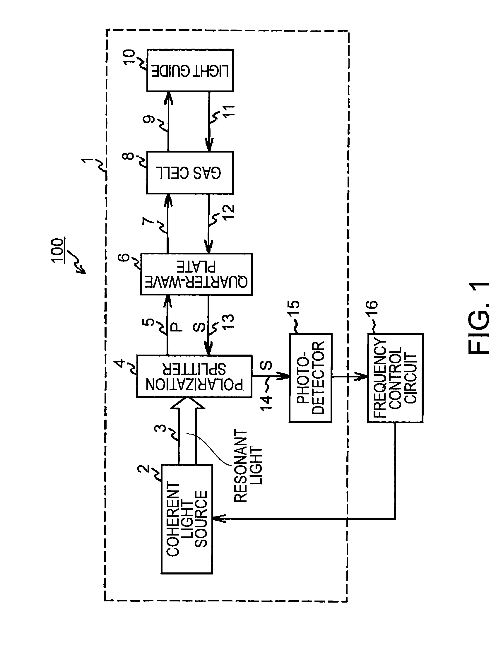
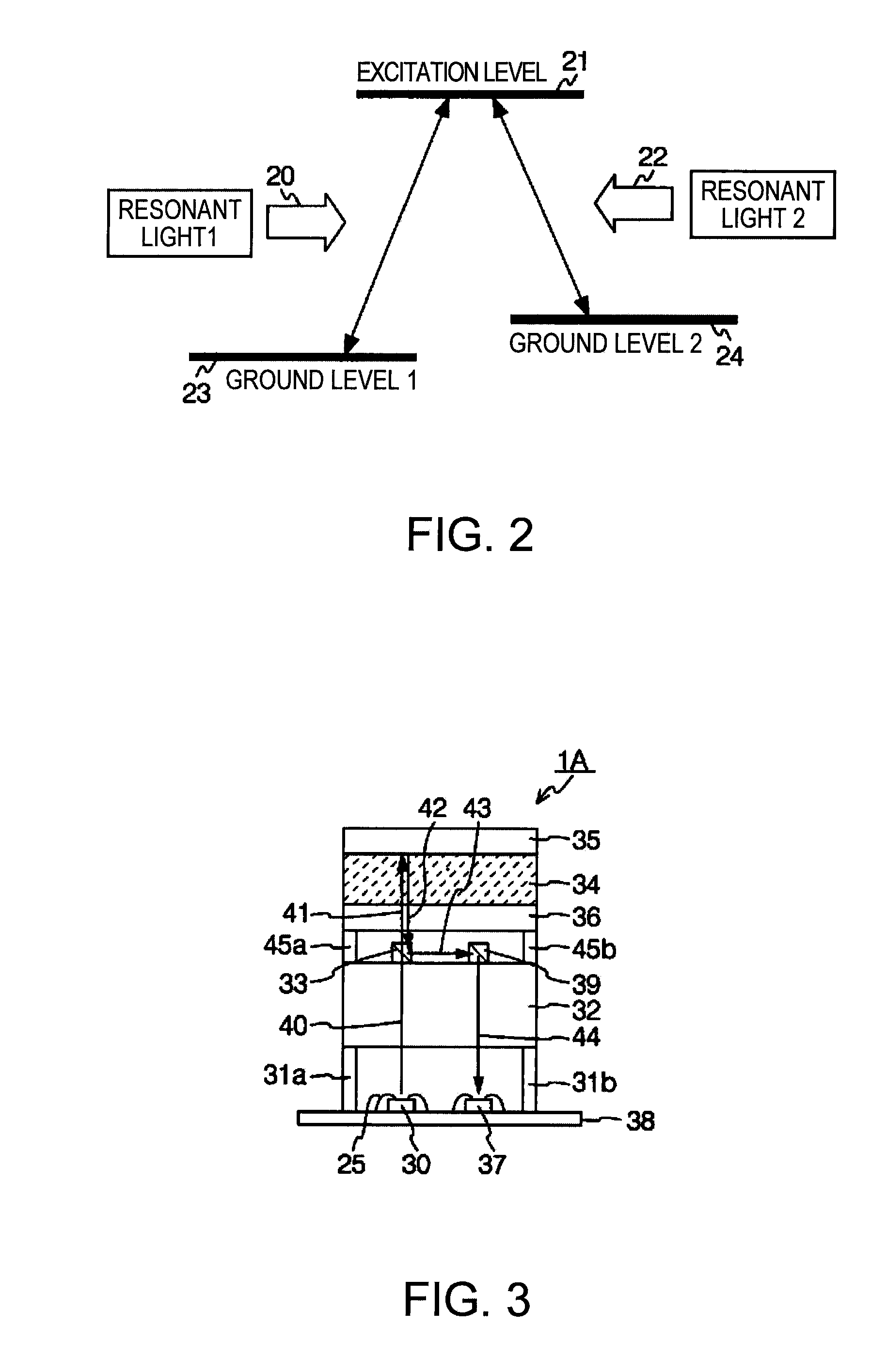
[0044]FIG. 3 is a schematic view illustrating the structure of an optical system according to the invention. An optical system 1A includes a light emitting element 30 (the coherent light source 2 in FIG. 1) and a light receiving element 37 (the photodetector 15 in FIG. 1) on a substrate 38, and each element is electrically coupled to the substrate 38 with a bonding wire 25. The optical system 1A further includes a passive optical device 32 that collects a coherent light 40 emitted from the light emitting element 30 so as to convert the coherent light 40 into collimated light and change the polarization state of the coherent light 40. Moreover, the optical system 1A includes, on the passive optical device 32, a beam splitter 33 and a second mirror 39 that guides s-polarized light to the substrate 38, the s-polarized light being changed the optical path by the beam splitter 33. Further, a quarter-wave (λ / 4) plate 36, a gas cell 34, and a first mirror 35 are layered above the second mi...

second embodiment

[0054]FIG. 4 is a schematic view illustrating the structure of an optical system according to the invention. The same reference numbers are used for elements similar to those described in FIG. 3. An optical system 1B includes a gas cell 46 and a first mirror 47 arranged within a range that covers an optical path. In other words, it is sufficient that the gas cell 46 and the first mirror 47 are included only in an optical path in which light passes.

[0055]Therefore, the gas cell 46 and the first mirror 47, located where light does not pass, are not essential. Therefore, in this embodiment, the gas cell 46 and / or the first mirror 47 is arranged only in the part that is designated to become the optical path. This enables reducing the size of the gas cell 46 and the first mirror 47 to a minimum, thereby reducing costs for components. Similarly, it is sufficient that the quarter-wave plate 36 is in the optical path, allowing the reduction of the size thereof.


PUM

PropertyMeasurementUnit
opticalaaaaaaaaaa
frequencyaaaaaaaaaa
optical pathaaaaaaaaaa

Abstract

An optical system of an atomic oscillator includes: a coherent light source emitting two resonant light components each having a p-polarized light component and an s-polarized light component, the tow resonant light components being coherent light and having a different frequency each other; a polarization splitter arranged at an output side of the coherent light source, the polarization splitter transmitting one of the p-polarized light component and the s-polarized light component and changes an optical path of the other of the p-polarized light component and the s-polarized light component to be outputted; a quarter-wave plate arranged at an output side of the polarization splitter so as to convert one of circularly polarized light and linearly polarized light to the other of circularly polarized light and linearly polarized light; a gas cell in which metal atom vapor is enclosed; a light guide that guides light after passing through the gas cell back to the gas cell as a turned-back light; and a photodetector that detects the turned-back light, the turned-back light having been passed through the gas cell and changed the optical path by the polarization splitter. The atomic oscillator controls an oscillation frequency by using a light absorption characteristic caused by a quantum-interference effect when the two resonant light components are incident on the optical system.

Description

BACKGROUND[0001]1. Technical Field[0002]The present invention relates to an optical system of an atomic oscillator, particularly to a mounting technique of a light source and a light receiving element included in the optical system constituting the atomic oscillator.[0003]2. Related Art[0004]Atomic oscillators using alkali metals such as rubidium and cesium include gas cells in which atoms are enclosed in an airtight manner, and those gas cells are operated in a high temperature for keeping the atoms in a gaseous form so that energy transition of atoms are utilized for atomic oscillator. Operating principles of atomic oscillators are broadly classified into two methods; a double resonance method that uses light and microwave, and a method that uses the quantum interference effect caused by two types of laser beams (hereafter referred to as “coherent population trapping” or CPT). In both methods, a detector installed on the side opposite to the gas cell detects how much light inciden...

Claims


Application Information

Patent Timeline
Patent Type & Authority Applications(United States)
IPC IPC(8): G01N21/61
CPCG04F5/145
Inventor NOMURA, HIROSHI
Owner SEIKO EPSON CORP
Why Eureka
Try Eureka