Stent manufacturing methods

Inactive Publication Date: 2009-05-28
ARTERIAL REMODELING TECH SA
View PDF13 Cites 7 Cited by
  • Summary
  • Abstract
  • Description
  • Claims
  • Application Information

AI Technical Summary

Benefits of technology

[0010]Certain preferred embodiments utilize what is best described as a two-dimensional, waffle mold where the mold is made of a silicone polymer. The resulting two-dimensional polymer sheet may be easily removed by stretching or twisting the m

Problems solved by technology

Unfortunately, the pressure exerted also traumatizes the artery, and in 30-40% of the cases the vessel either gradually renarrows or recloses at the locus of the original stenotic lesion.
Although metallic stents have the mechanical strength necessary to prevent the retractile form of restenosis, their presence in the artery can lead to biological problems including vasospasm, compliance mismatch, and even occlusion.
Moreover, there are inherent, significant risks from having a metal stent permanently implanted in the artery, including actual erosion or destruction of the vessel wall.
The stents may also migrate on occasion from their initial insertion location raising the potential for stent-induced blockage.
Metal stents, especially if migration occurs, cause irritation to the surrounding tissues in a lumen.
Also, since metals are typically much harder and stiffer than the surrounding tissues in a lumen, this may result in an anatomical or physiological compliance mismatch, thereby damaging tissue or eliciting unwanted biologic responses.
In addition, the constant exposure of the stent to the blood can lead to thrombus formation within the blood vessel.
Further, metal stents typically have some degree of negative recoil.
This method, however, may lead to the polymer being thermally damaged during the extrusion process.
This method poses many problems because the film

Method used


Image

  • Stent manufacturing methods
  • Stent manufacturing methods
  • Stent manufacturing methods

Examples


Embodiment Construction

Definitions

[0033]“Bioresorbable polymer” as used herein refers to a polymer whose degradation by-products can be bio-assimilated or excreted via natural pathways in a human body.

[0034]“Acetone bath” as used herein refers to a bath comprising one or more solvents, where the solvents may be acetone, chlorinated hydrocarbons, and / or ketones. Certain preferred embodiments of the polymeric stent fabrication method include partially or fully immersing the polymeric stent into the acetone bath.

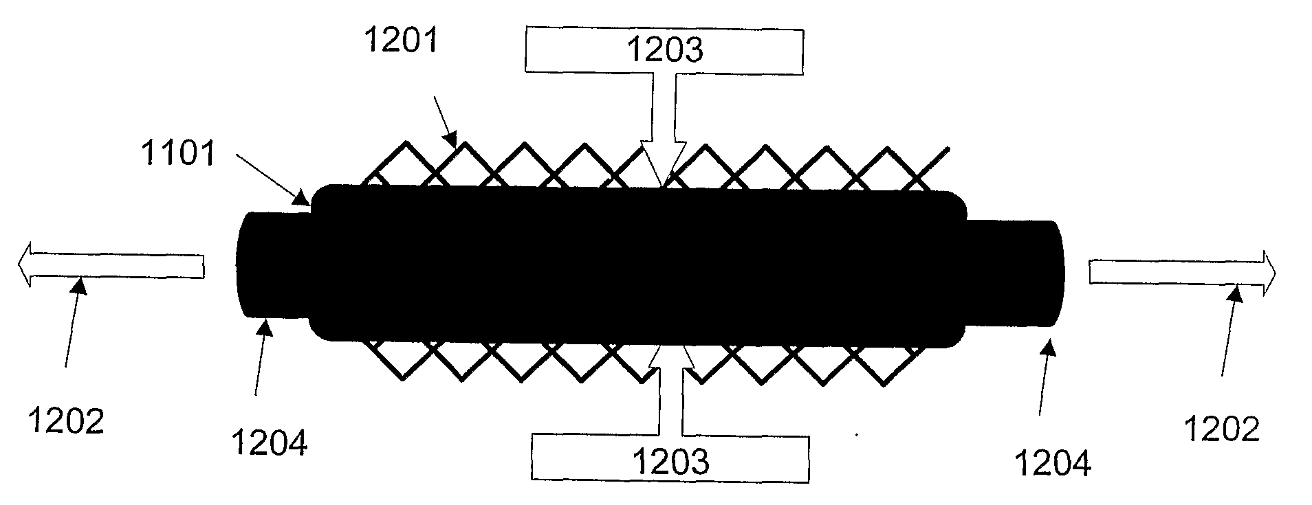
[0035]“Crimping” as used herein refers to a process that involves pressing, preferably radially, on a polymeric cylindrical device having slits, or openings in the wall thereof to allow a decrease in the diameter of the device without substantially affecting the thickness of the wall or struts of the cylindrical device. Such process, typically also results in an increase in length of the cylindrical device.

[0036]“Degradable polymer” or “biodegradable polymer” as used herein refers to a polymer that b...


PUM

PropertyMeasurementUnit
Glass transition temperatureaaaaaaaaaa
Lengthaaaaaaaaaa

Abstract

A novel method of manufacturing stents by use of molds (1101) made of a biocompatible, flexible material, preferably silicone. Some embodiments use silicone polymers; a two-dimensional, waffle mold; injection molds whereby the core of the injection mold is silicone polymer. In some embodiments, the stent polymer or particles of stent polymers are injected into the mold, around a cylinder of silicone, to form a three-dimensional stent. In some embodiments, particles of silicone polymer are mechanically forced into the negative spaces and then fused together to form the finished product. In other embodiments, metal stents or metal molds are used to manufacture a reverse mold. The reverse mold (901) is then used to create positive silicone molds. The silicone molds can subsequently be used by any means to make polymer stents, lending themselves to automation.

Description

BACKGROUND OF THE INVENTION[0001]The use of stents in various surgical, interventional cardiology, and radiology procedures has quickly become accepted as experience with stent devices accumulates and as the advantages of stents become more widely recognized. Stents are often used in body lumens to maintain open passageways such as the prostatic urethra, the esophagus, the biliary tract, intestines, and various coronary arteries and veins, as well as more remote cardiovascular vessels such as the femoral artery.[0002]Stents are often used to treat atherosclerosis, a disease in which vascular lesions or plaques consisting of cholesterol crystals, necrotic cells, lipid pools, excess fiber elements, and calcium deposits accumulate in the walls of an individual's arteries. One of the most successful procedures for treating atherosclerosis is to insert a deflated balloon within the lumen, adjacent the site of the plaque or atherosclerotic lesion. The balloon is then inflated to put press...

Claims


Application Information

Patent Timeline
IPC IPC(8): B32B37/00B29C39/00
CPCA61F2/82B29L2031/7532B29C33/405B29C33/424B29C33/50B29C39/006B29C39/24B29C39/34B29C41/36B29C41/386B29C45/261B29C45/372B29K2067/043B29K2067/046B29K2995/006B29C33/3878
Inventor SABARIA, PATRICK
Owner ARTERIAL REMODELING TECH SA
Why Eureka
Try Eureka