

Method for synthesis of carbon nanotubes
a carbon nanotube and carbon nanotube technology, applied in the direction of nanostructure manufacturing, liquid gas reaction process, non-conductive material with dispersed conductive material, etc., can solve the problem of difficult to impregnate large quantities of iron, iron acetylacetonate is less effective than iron nitrate, and swnts are more difficult to manufacture than mwnts
- Summary
- Abstract
- Description
- Claims
- Application Information
AI Technical Summary
Benefits of technology
Problems solved by technology
Method used
Image

Examples
example 1
Comparative Example—Preparation of CNTs by CVD According to the Prior Art: Step a) Only
[0055]A catalyst consisting of 35% iron was prepared by impregnating a Puralox SCCA 5-150 γ-alumina, having a median diameter of about 85 μm, with an iron nitrate solution. The impregnation was carried out in a fluidized bed with an air stream at 100° C. in order to keep the powder dry throughout the operation. 300 g of this catalyst were introduced as a layer in a 25 cm diameter reactor with an effective height of 1 m, the reactor being fitted with a disengagement device intended to prevent particle fines (fine catalyst particles) from being entrained downstream. The reactor was heated for 40 minutes at 300° C. under nitrogen, and then under hydrogen / nitrogen (20 vol % / 80 vol %), increasing the temperature up to 650° C. over 75 minutes. At this temperature, a 3000 Nl / h stream of ethylene and a 1000 Nl / h stream of hydrogen were introduced, this corresponding to an ethylene partial pressure of 0.75...
example 2
According to the Invention—Ex Situ Milling
[0060]The product obtained in Example 1 was subjected to tangential air jet milling in an apparatus sold by Alpine under the name Spiral jet mill 50 AS.
[0061]The gas flow rate and the injection time were set so as to reduce the agglomerates obtained according to Example 1 with a d50 of 40 μm.
[0062]A 5 g specimen of this milled product was introduced, under the CNT synthesis conditions according to Example 1, with an ethylene / hydrogen volume ratio of 3 / 1, into a 5 cm diameter reactor.
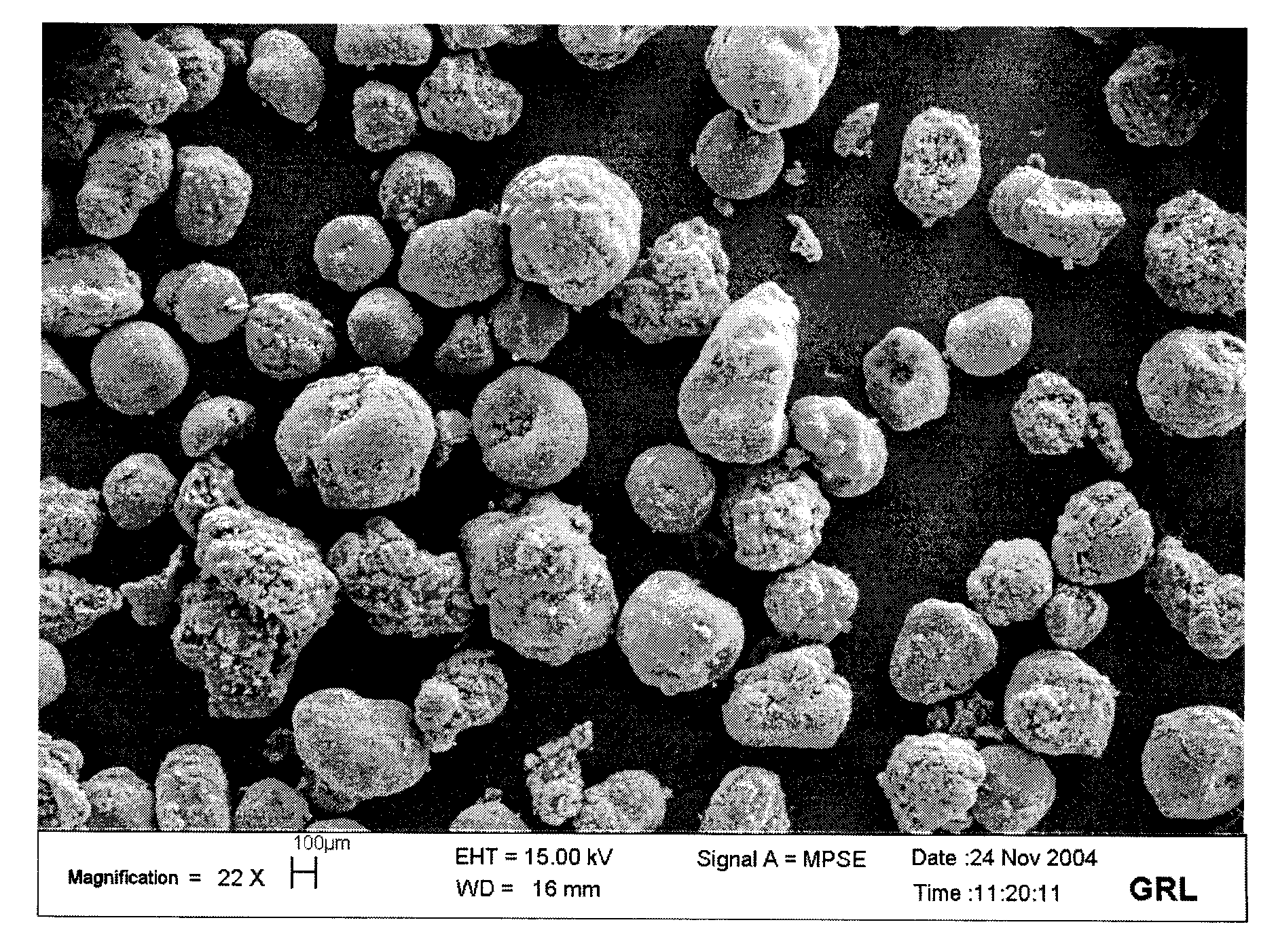
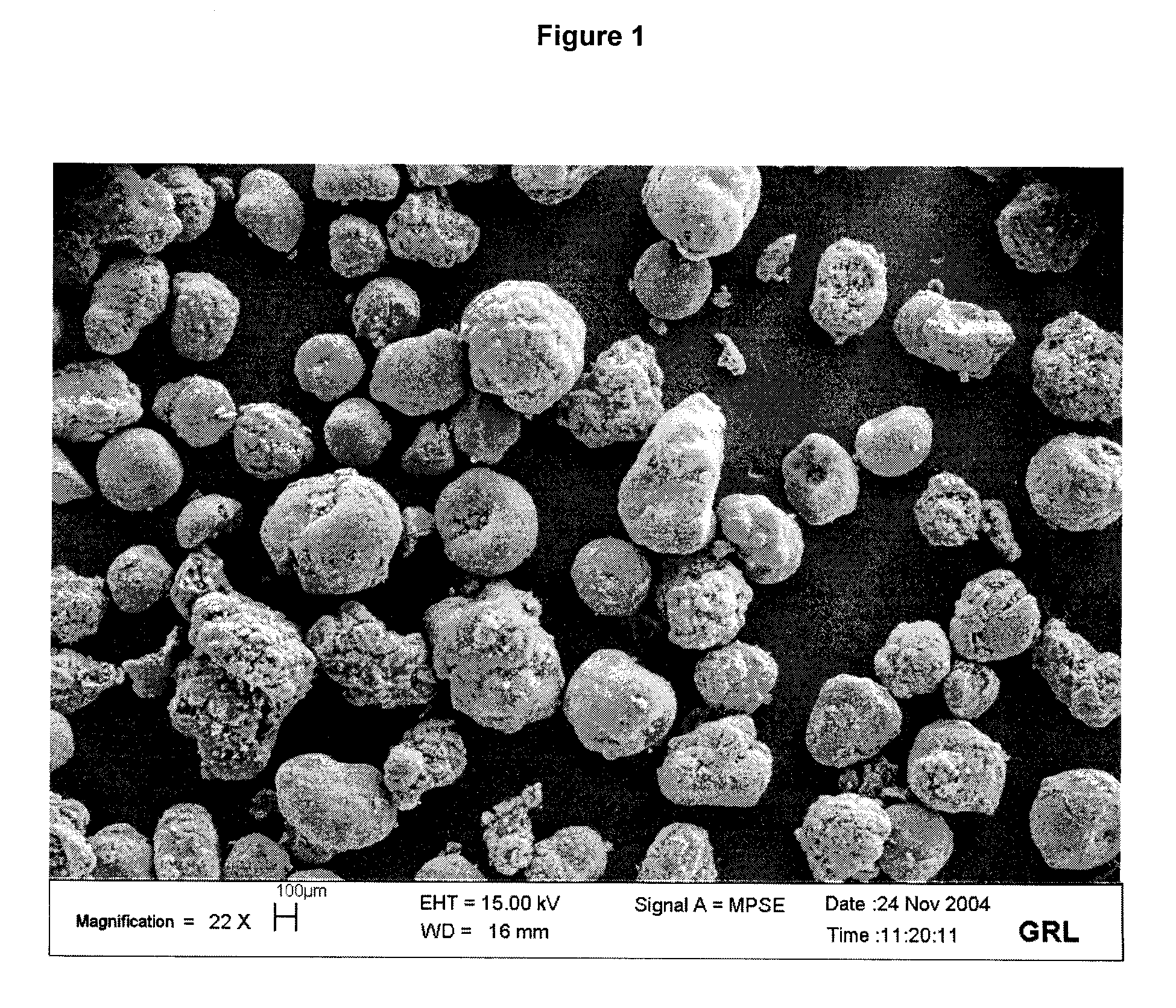
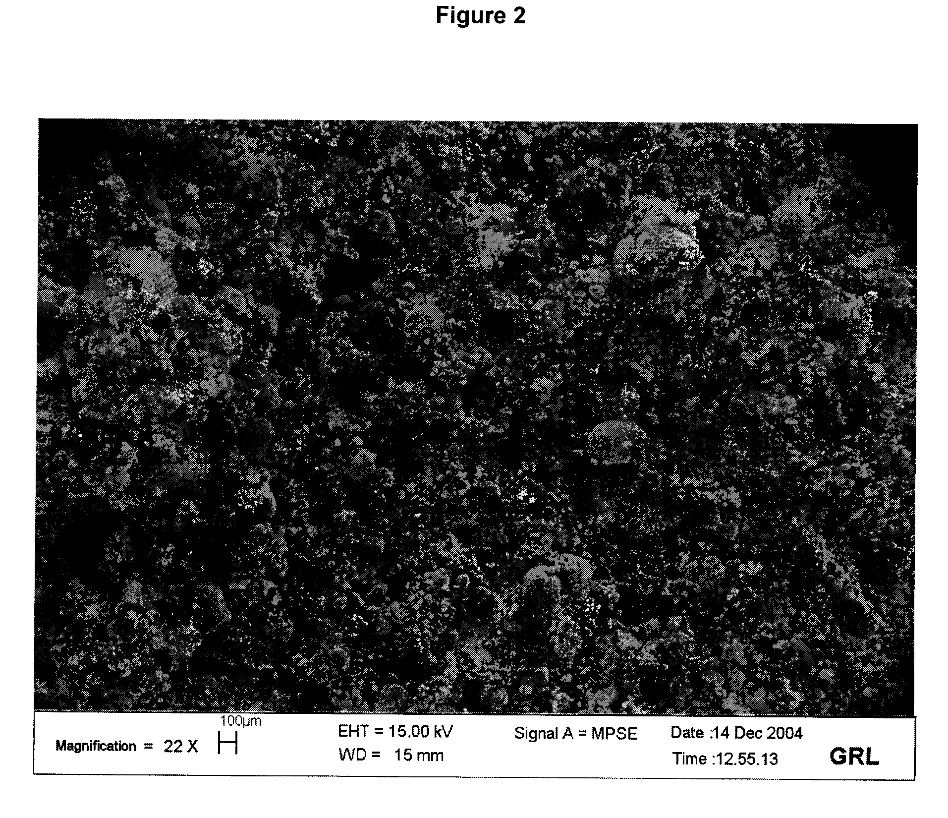
[0063]By comparing FIG. 2 with FIG. 1, it may be clearly seen that the process according to the invention results in a very small number of CNT agglomerates with a diameter greater than 200 μm. The final product thus formed is therefore more easily dispersed within a material, in particular a polymer.
[0064]At the end of synthesis, 6.4 g of final product were recovered, i.e. an increase of 28% (100×(6.4−5) / 5) with respect to the quantity of product introduced. The...
example 3
According to the Invention—In Situ Milling
[0065]The product obtained in Example 1 was subjected to air jet milling directly in the synthesis reactor according to FIG. 3 appended hereto.
[0066]The milling was carried out at room temperature in the CNT synthesis reactor (6), which was a vertical tube 5 cm in diameter fitted with a porous distributor (3) equipped with a nozzle (2) for introducing high-velocity gas. The medium (7) was fluidized by a nitrogen stream (1) flowing through the distributor and a second stream (2a) passing through the nozzle (1).
[0067]The gas flow rate and the injection time were set to reduce the agglomerates obtained according to Example 1 with a d50 of 40 μm.
[0068]The final product thus obtained can be dispersed easily and homogeneously in a polymeric material, for the purpose of modifying its mechanical, electrical and / or thermal properties.
PUM
| Property | Measurement | Unit |
|---|---|---|
| Temperature | aaaaa | aaaaa |
| Temperature | aaaaa | aaaaa |
| Electrical conductivity | aaaaa | aaaaa |
Abstract
Description
Claims
Application Information