[0009]A first object of this invention is to provide a pedicle
screw placement device that accurately positions a pedicle screw centrally within the
bone mass of the pedicle, thereby preventing the pedicle screw from reaching too close to the
nerve cells of the
spinal column or being too close to the external surface of the bone, and thus to avoid cracks on the
bone surface that could compromise the integrity of the
pedicle screw fixation.
[0011]A further object is to provide a method of pedicle screw placement that is a relatively simple routine technique that less experienced professionals can employ safely.
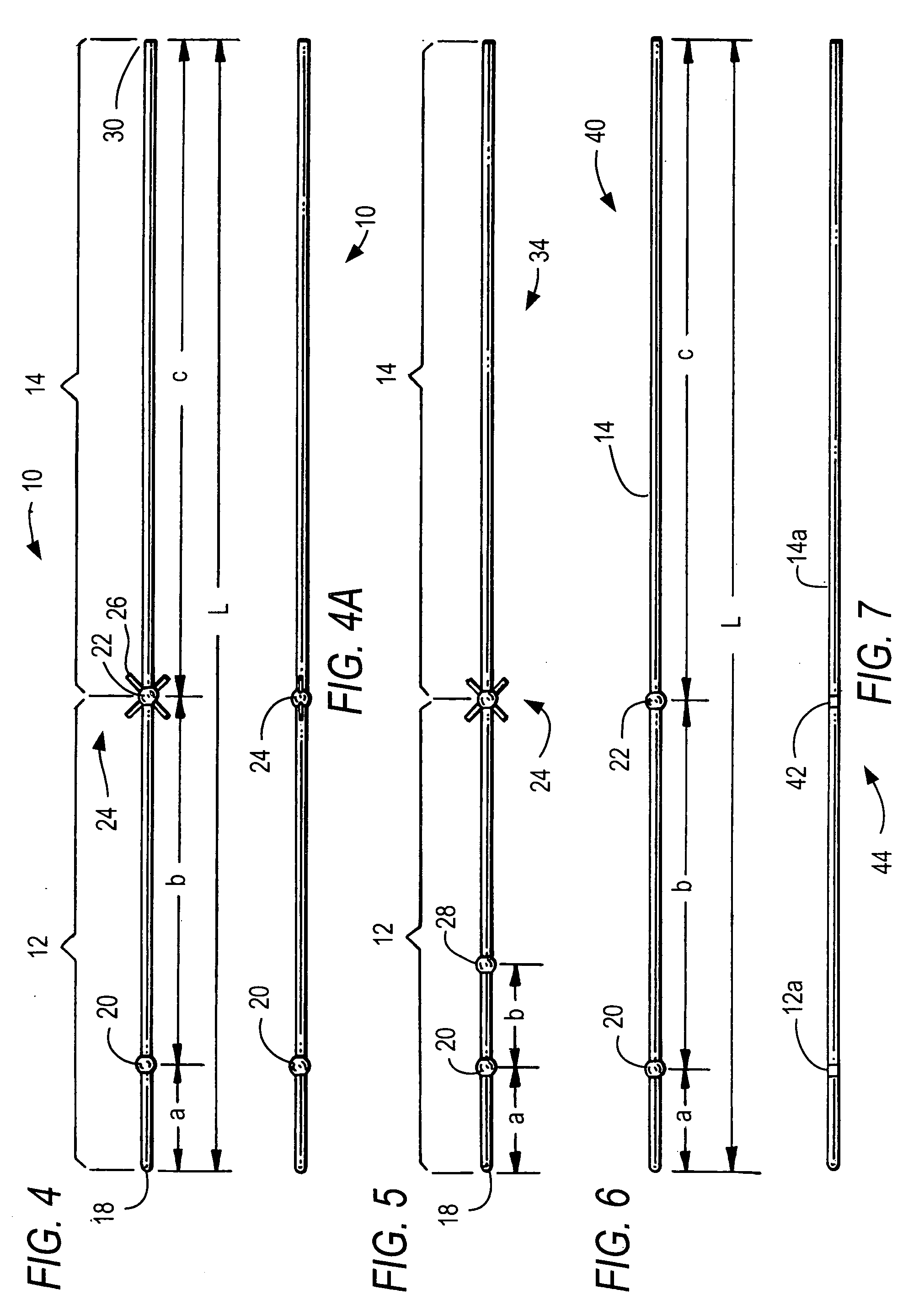
[0015]It is a further object for the new pedicle screw placement device to be a single thin, elongated radiopaque guide pin of predetermined length with at least one radiopaque marker situated at a predetermined distance from its distal end so that from X-
ray radiographs a surgeon can determine if the trajectory is safe and can determine the preferred length and
diameter for the pedicle screw.
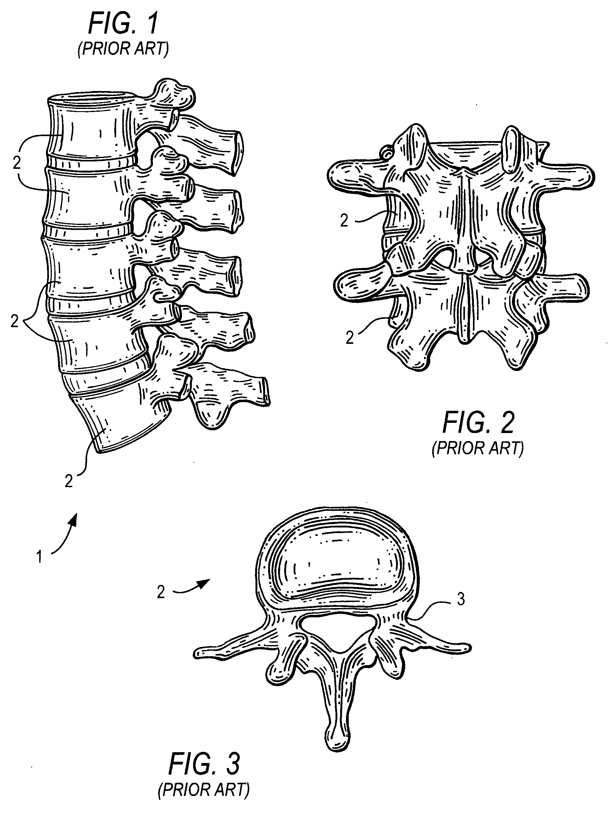
[0017]It is thus an object of the present invention to provide a device and method for pedicle screw placement that improves the accuracy of positioning a pedicle screw into the pedicle of a vertebra as part of a
spinal fusion procedure.
[0027]In said various embodiments of guide pins the tip of said
distal portion of the guide pin, whether it is rounded or sharp, is adapted to be easily inserted into an
entry point of the pedicle bone. The cross-sectional shape of this
distal portion may be circular, oval, elliptical, rectangular or any suitable cross-section of
diameter of about 1.5 to 3 mm, and the length may be up to about 20 cm, and preferably about 2 cm. The
distal portion may be tapered in the proximal direction to have a larger diameter for easier penetration of the guide pin and for improved x-
ray radiograph image
visibility. Each radiopaque marker is typically a spherical section to allow ease of
insertion and to improve guide pin x-
ray image
visibility as it extends through the pedicle and facilitates identification of the pedicle isthmus. These guide pins are relatively stiff and may be made of any radiopaque material, examples including stainless steel, preferably 316 L or 304,
titanium,
titanium composites or
titanium alloy, or mixtures of the above.
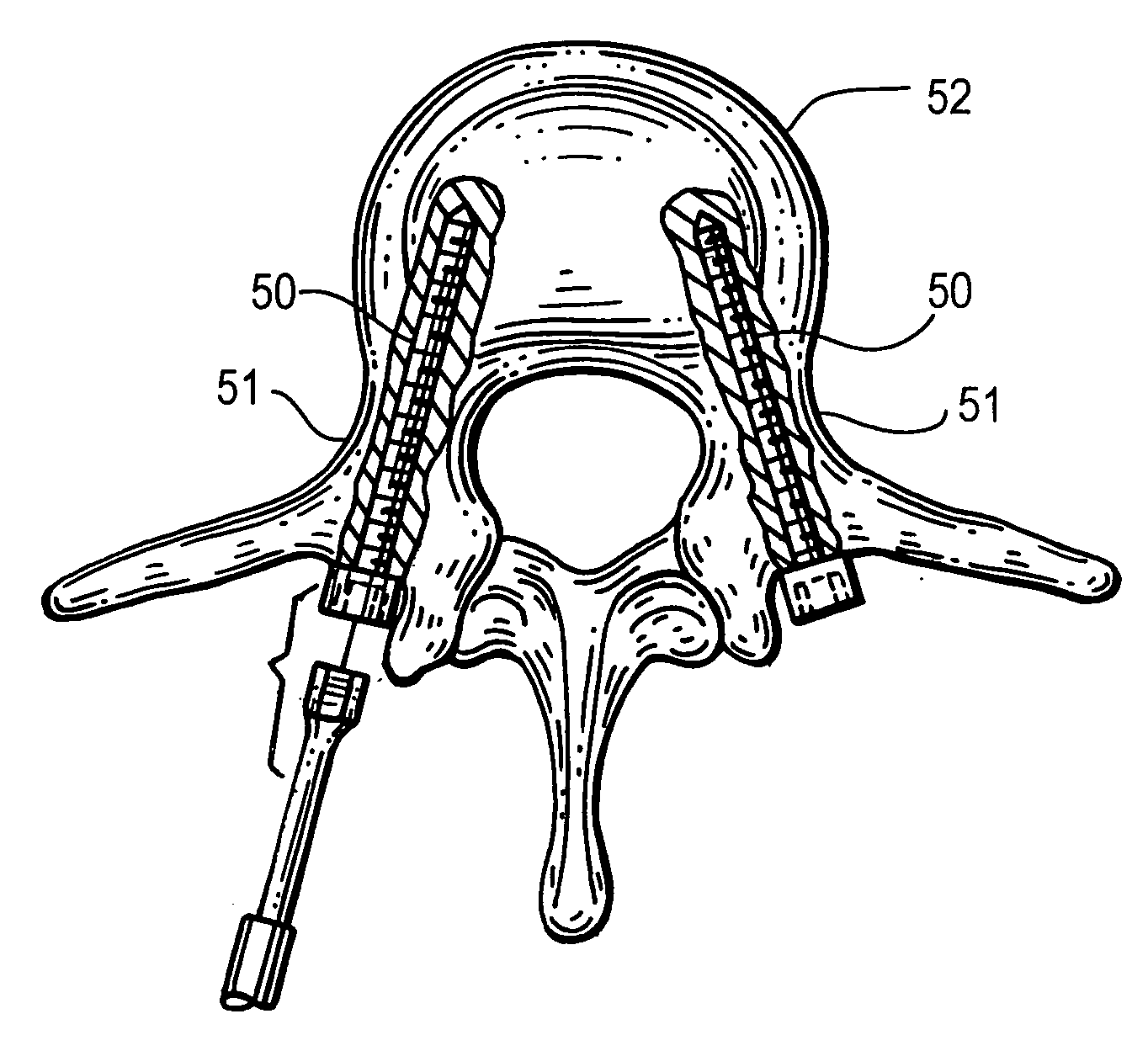
[0033]In accordance with the new method, after the guide pins are initially placed the patient is taken for x-ray
radiography where two orthogonal radiographs are taken, typically one radiograph providing a vertical image and a second radiograph providing a lateral horizontal image, producing posteroanterior and lateral x-ray images. The radiographs image both the interior structure of the pedicle bone and the inserted guide pin with its first, second sections as well as the X-shaped marker stop element. The X-shaped marker represents exactly the guide pin
insertion point at the pedicle
bone surface of the patient, while the imaged guide pin first and second sections and any radiopaque markers thereon show how the guide pin is oriented within the interior pedicle
bone structure of the patient. With this procedure it is easy to observe if the inserted tip of the guide pin is too close to the
spinal canal of the pedicle or too close to the external surface of the pedicle
bone surface. If the pedicle screw inserted at the guide pin were to touch the
spinal cord, nerve damage could result resulting in
paralysis or other complications. Similarly, if the pedicle screw intersects the external surface of the pedicle bone, cracks could form compromising the integrity of
pedicle screw fixation process. Ideally, the guide pin should be located on a centerline between these two angular extremes. The surgeon observes this centerline orientation and any angular misalignment in the
vertical plane and horizontal plane by studying the two X-ray images. If misalignment exists the surgeon withdraws the guide pin and reinserts it in a new selected
angular orientation, preferably still using the same entry point, and then produces two additional orthogonal radiographs to confirm the angular re-orientation of the guide pin, which is now located in the desired centerline of the pedicle
bone structure. The length of the pedicle screw needed is easily estimated using
radiography to compare the known distances between markers and the observed
bone structure.

