Eureka AIR delivers breakthrough ideas for toughest innovation challenges, trusted by R&D personnel around the world.

Numerical controller having control mode switching function

a technology of control mode and controller, applied in the field of numerical controller, can solve the problems of increasing the machining cycle time, and achieve the effects of reducing the machining time of workpieces, improving productivity, and high cos

Active Publication Date: 2009-06-18
FANUC LTD
View PDF10 Cites 8 Cited by
  • Summary
  • Abstract
  • Description
  • Claims
  • Application Information

AI Technical Summary

Benefits of technology

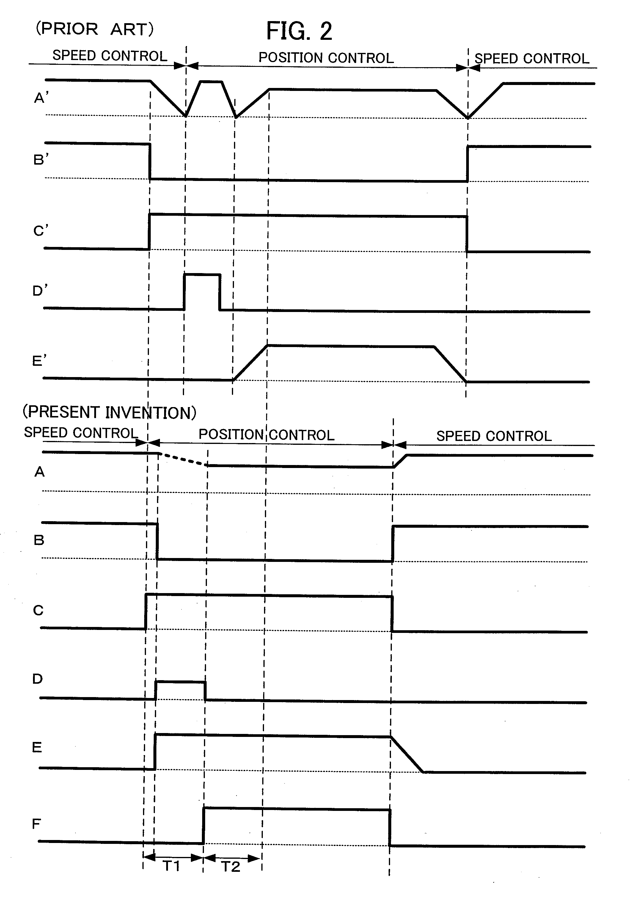
[0015]An object of the present invention is to provide a numerical controller that requires less time for workpiece machining by eliminating the need for the deceleration and stop of a spindle during switching of the control of a spindle motor from speed control to position control.
[0019]As the numerical controller of the present invention has the structure described above, the spindle does not have to be decelerated or stopped during switching of the control of the spindle motor from speed control to position control, thereby achieving reduction in workpiece machining time and improvement of productivity.
[0020]The numerical controller of the present invention can achieve the similar machining cycle time as in the prior art by using a low-cost spindle motor with low acceleration / deceleration capability, not using a high-cost spindle motor with high acceleration / deceleration capability. In addition, the number of times the spindle motor is accelerated or decelerated can be reduced, thereby saving the power consumption during a workpiece machining process.
[0021]According to the present invention, an interpolation between an axis switched to the position control and the other axes will produce a non-cutting command portion until movement to the position control start reference position is completed, since the synchronization among these axes is not guaranteed, but the cycle time can be reduced in the entire machining program.

Problems solved by technology

However, switching from speed control mode to position control mode takes much time, thereby increasing machining cycle time.

Method used


Image

  • Numerical controller having control mode switching function
  • Numerical controller having control mode switching function
  • Numerical controller having control mode switching function

Examples


Embodiment Construction

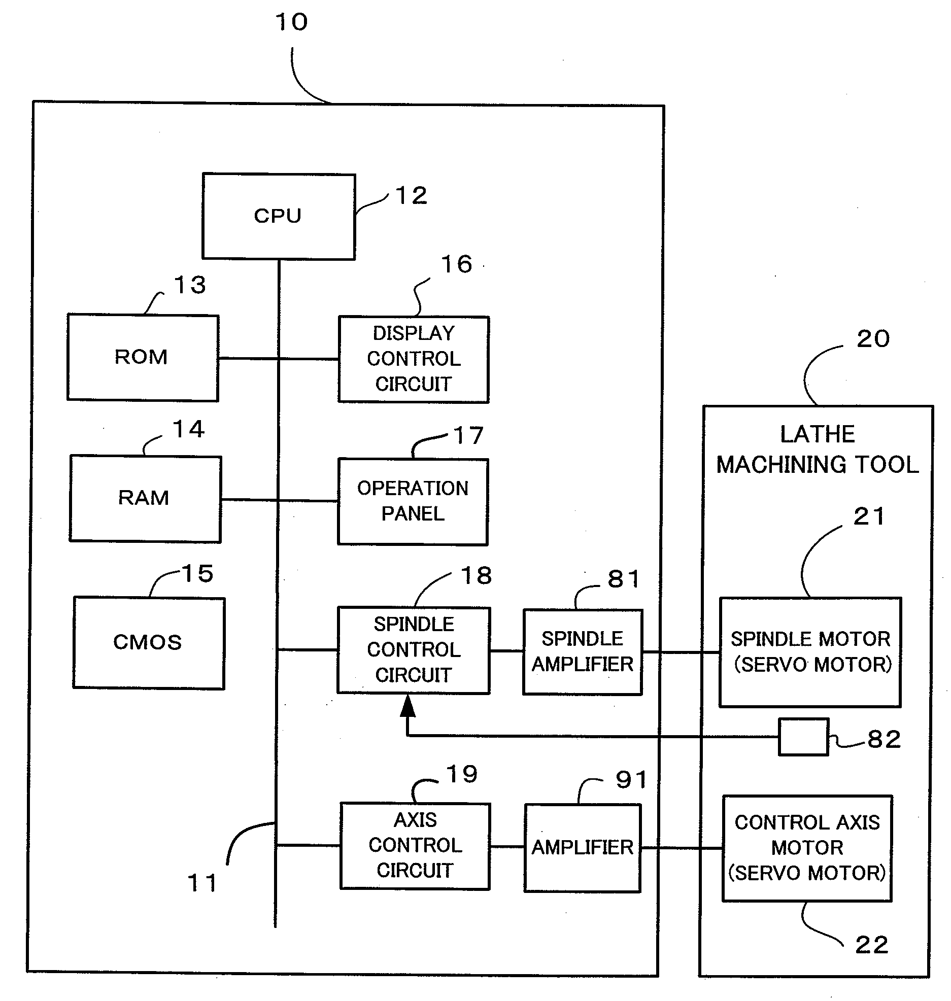
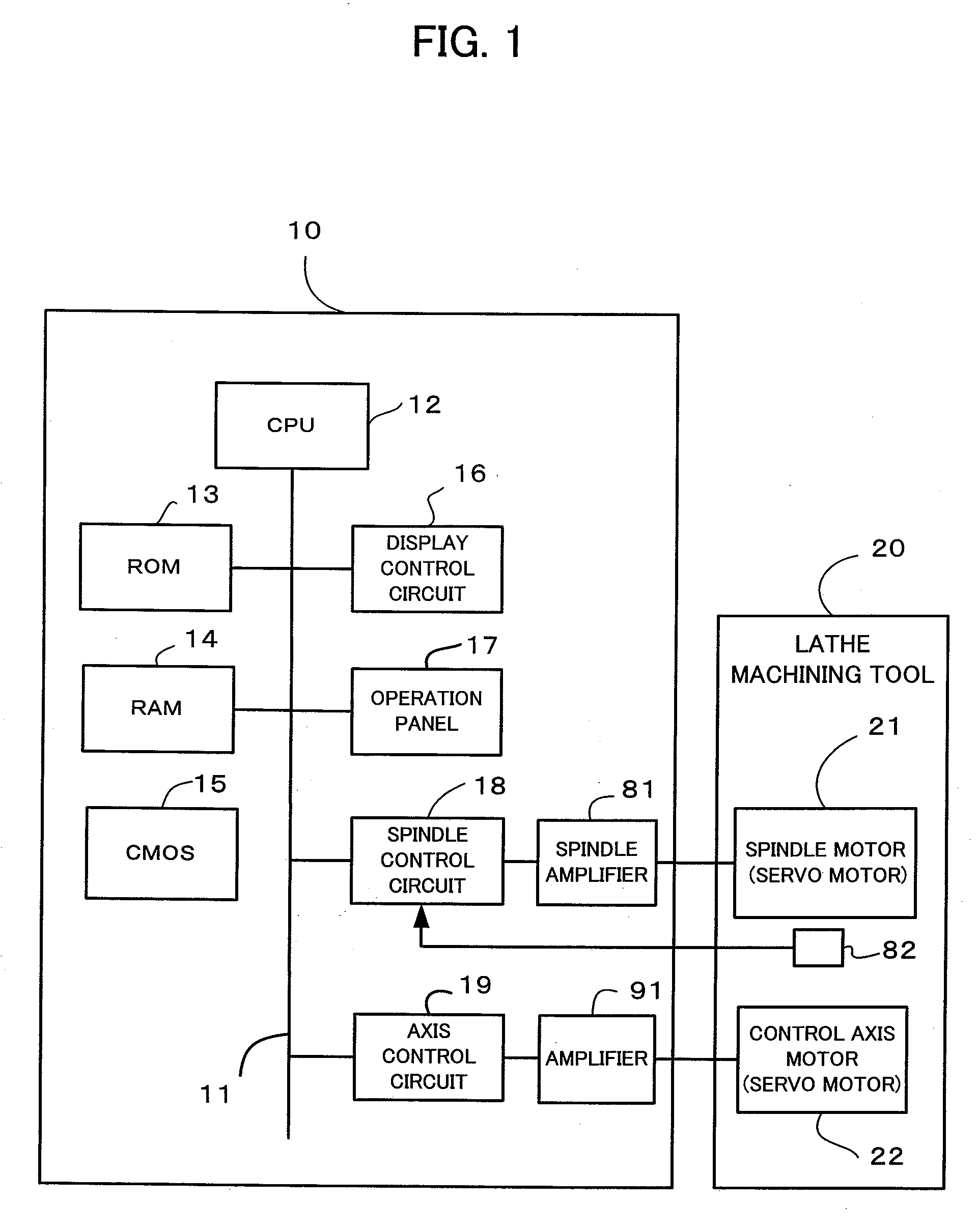
[0033]FIG. 1 is a schematic diagram of a numerical controller 10. The numerical controller 10 comprises a processor (CPU) 12, a ROM 13, a RAM 14, a CMOS memory 15, a display control circuit 16, an operation panel 17, a spindle control circuit 18, an axis control circuit 19, and a bus 11. The CPU 12 reads out a system program stored in the ROM 13 via the bus 11 and controls the entire numerical controller 10 according to the system program. The RAM 14 temporarily stores computation data and display data, and also stores various types of data input by an input means (not shown). The ROM 13 stores various system programs and editing functions required to create and edit machining programs, in advance. The CMOS memory 15 is backed up by a battery (not shown) and configured as a non-volatile memory that retains stored data even when the numerical controller 10 is powered off. The CMOS memory 15 stores machining programs etc.

[0034]The spindle control circuit 18 receives a spindle rotation...


PUM


Abstract

A pulse distribution unit notifies a mode control / instruction unit of an output start signal Sa that notifies of the start of output of a position command signal. The mode control / instruction unit outputs a mode setting signal, a speed command signal, and a compensation pulse Sc to an axis control unit. In a position control mode, the mode control / instruction unit continues outputting the speed command signal to the axis control unit until the mode control / instruction unit receives the output start signal Sa from the pulse distribution unit, and stops, up receiving the output start signal Sa, outputting the speed command signal. The compensation pulse Sc is output to the axis control unit to cancel the difference between a spindle position and the position control start reference position of the spindle. The axis control unit adds the compensation pulse Sc to the position command signal of the spindle output from the pulse distribution unit and outputs the result to a servo control unit.

Description

BACKGROUND OF THE INVENTION[0001]1. Field of the Invention[0002]The present invention relates to a numerical controller having a function of switching the control mode of a spindle motor between a speed control mode and a position control mode.[0003]2. Description of the Related Art[0004]A piston lathe machine for out-of-round (elliptical) workpiece machining repeats a lot of piston-shaped workpiece machining by performing the following two types of machining in sequence.[0005](1) Performing round turning for an outside shape of a piston or a groove for a piston ring by rotating a workpiece spindle driven by a spindle motor with an S command (hereinafter referred to as speed control)[0006](2) Executing a movement command for a workpiece spindle and an axis that performs cut-in operation with a machining program by switching the control mode of the workpiece spindle driven by the spindle motor to a position control mode. In this case, out-of-round cutting is performed by synchronizin...

Claims


Application Information

Patent Timeline
IPC IPC(8): G05B7/02
CPCG05B2219/42104G05B19/19
Inventor HOSOKAWA, MASAHIKOOGAWA, SHUJISONOBE, KAZUHIKO
Owner FANUC LTD
Why Eureka
Eureka Blog
Learn More